
Electronic connector and manufacturing method thereof

A technology for electronic connectors and manufacturing methods, which is applied in the direction of connection, contact manufacturing, and parts of connecting devices, etc., and can solve the problems of electronic connectors not being available

Inactive Publication Date: 2021-02-23
昆山元太金精密工业有限公司
View PDF6 Cites 0 Cited by
  • Summary
  • Abstract
  • Description
  • Claims
  • Application Information

AI Technical Summary

Problems solved by technology

Most of the existing electronic connector manufacturing methods are stamping, electroplating, injection molding and assembly. The electronic connectors produced basically have a fixed model structure, and the structure is fixed and the method is fixed. It is aimed at the different use environments of the current electronic connectors. , the required types and models are various, and the existing electronic connectors do not have the option to adjust the quantity. The present invention also improves the manufacturing method of the electronic connectors under the condition of changing the original structure. This proposes an electronic connector and a manufacturing method thereof

Method used

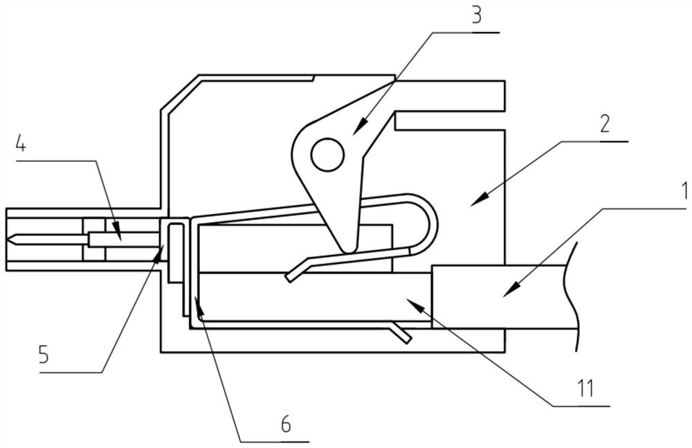
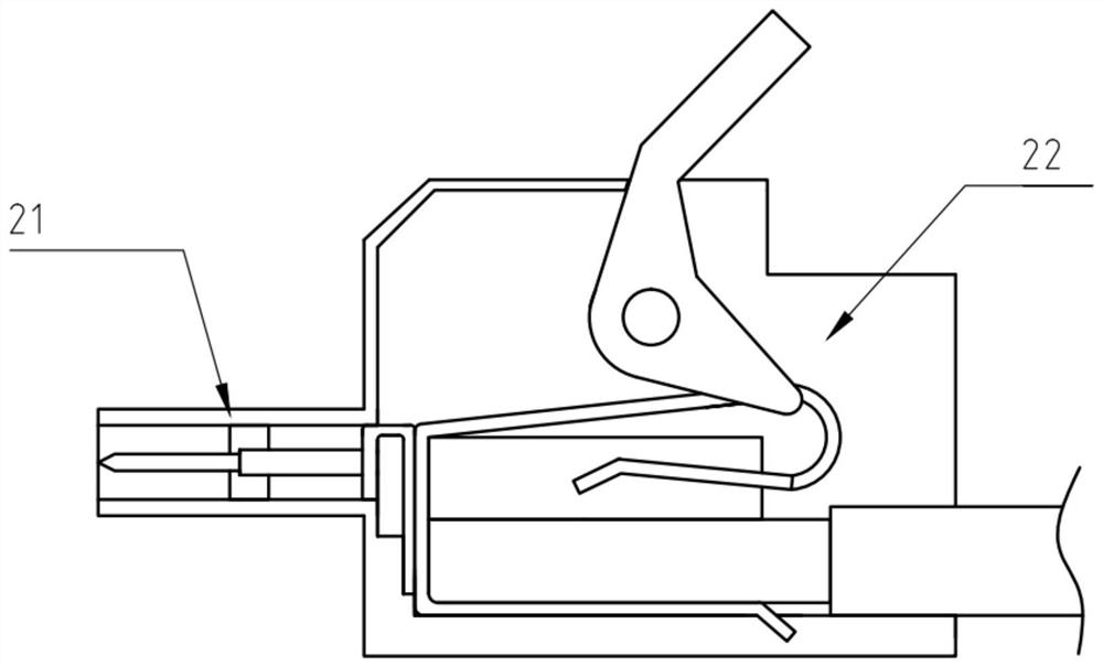
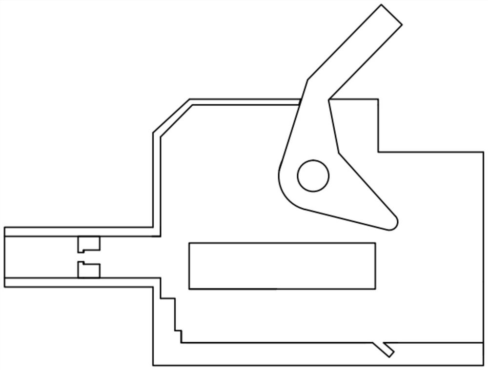

Image

  • Electronic connector and manufacturing method thereof
  • Electronic connector and manufacturing method thereof
  • Electronic connector and manufacturing method thereof

Examples


Embodiment Construction

[0024] The technical solutions in the embodiments of the present invention will be clearly and completely described below in conjunction with the accompanying drawings provided by the embodiments of the present invention. Obviously, the described embodiments are only preferred embodiments of the present invention, not all implementations. example. Based on the preferred embodiments of the present invention, all other embodiments obtained by persons of ordinary skill in the art without making creative efforts belong to the protection scope of the present invention. The present invention will be described in further detail below.

[0025] In the description of the present invention, it should be understood that the orientations or positional relationships indicated by the terms "upper", "lower", "top", "bottom", "inner" and "outer" are based on those shown in the accompanying drawings. Orientation or positional relationship. The foregoing definitions are only for the convenien...


PUM


Abstract

The invention discloses an electronic connector which comprises an injection molding shell, a profiling inner cavity is formed in the injection molding shell, an outwards-extending connecting end is arranged at the front end of the injection molding shell, a PIN is arranged in the outwards-extending connecting end, the sharp section of the PIN faces the side away from the profiling inner cavity, and a connecting gasket is connected to the tail end of the PIN in an attached mode. The connecting gasket is fixed in the profiling inner cavity, the other end of the connecting gasket is connected with a limiting connecting piece in an attached mode, the limiting connecting piece is bent and fixed in a clip mode, and the limiting connecting piece is connected with the connecting gasket in a contact mode and fixed in the profiling inner cavity. The limiting connecting piece is used for being connected with an electric wire with the exterior stretching into the profiling inner cavity. Connection and fixation are achieved through an independent structure, and the locking function is achieved.

Description

technical field [0001] The invention particularly relates to an electronic connector and a manufacturing method thereof. Background technique [0002] State of the art: Electronic connectors are also often called circuit connectors, electrical connectors, and bridges two conductors on a circuit so that current or signals can flow from one conductor to another conductor. An electronic connector is an electronic system that provides a separable interface to connect two sub-electronic systems, in short, to complete the connection between circuits or electronic components. Most of the existing electronic connector manufacturing methods are stamping, electroplating, injection molding and assembly. The electronic connectors produced basically have a fixed model structure, and the structure is fixed and the method is fixed. It is aimed at the different use environments of the current electronic connectors. , the required types and models are various, and the existing electronic co...

Claims


Application Information

Patent Timeline
Patent Type & Authority Applications(China)
IPC IPC(8): H01R13/405H01R43/16H01R43/24
CPCH01R13/405H01R43/16H01R43/24
Inventor 伍志宏
Owner 昆山元太金精密工业有限公司
Learn More