Split type brake disc

A brake disc, split technology, applied in the direction of the brake disc, brake type, brake components, etc., can solve the problem of the vehicle not running normally and the high cost of replacement and maintenance

Active Publication Date: 2020-08-28
CRRC CHANGZHOU TECH MARK IND CO LTD +1
View PDF9 Cites 3 Cited by
  • Summary
  • Abstract
  • Description
  • Claims
  • Application Information

AI Technical Summary

Problems solved by technology

If the method of integrally lowering the bogie, withdrawing the wheels, withdrawing the disc, and then replacing the integral brake disc will cause the vehicle to fail to operate normally, and the cost of replacement and maintenance will be high. Therefore, it is necessary to develop a split system that meets the requirements of vehicle connection and heat capacity. rotor for direct replacement of failed brake discs

Method used


Image

  • Split type brake disc
  • Split type brake disc
  • Split type brake disc

Examples


Embodiment 1

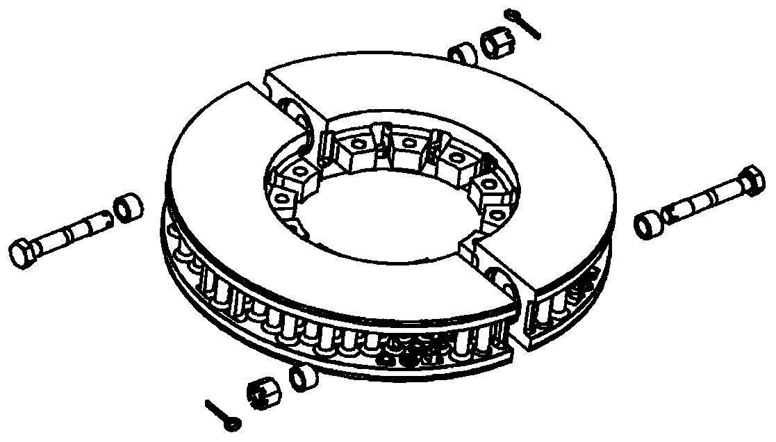
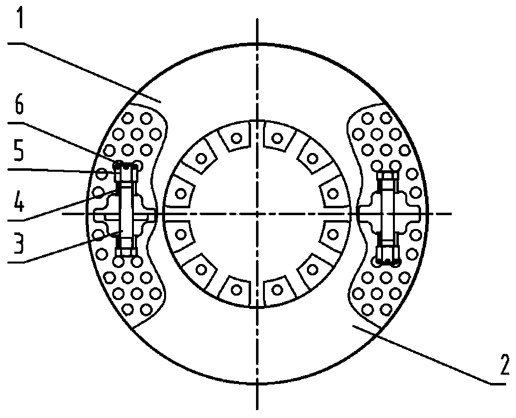
[0080] Such as Figure 1-7 As shown, the split brake disc of the present invention has two sub-disc bodies, namely the first sub-disc body 1 and the second sub-disc body 2, the first connecting piece is a bolt 3, which also includes a spacer 4 , nut 5, cotter pin 6. Wherein the first sub-disc body 1 and the second sub-disc body 2 are both half disc bodies, and the nut 5 is a slotted locking nut.

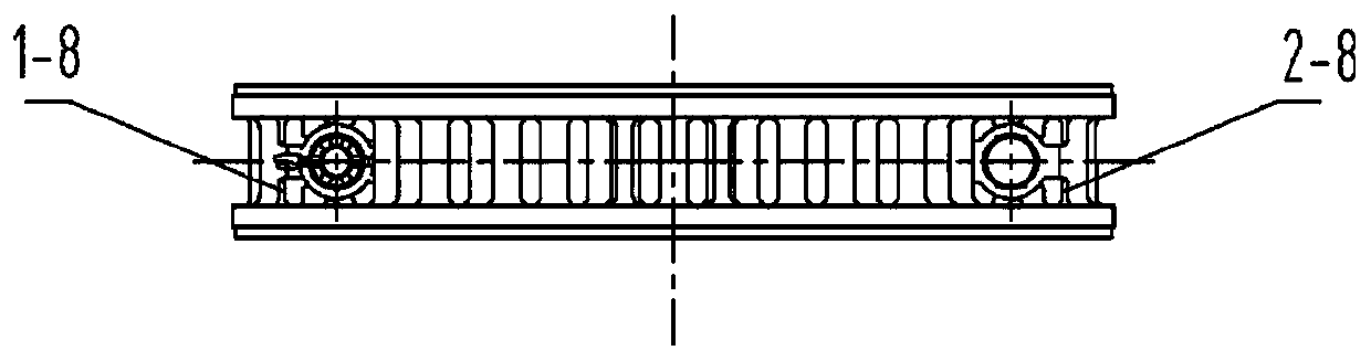
[0081] Wherein, the first sub-disc body 1 is composed of two semicircular first sub-disc body friction rings 1-1, the first sub-disc body first cooling ribs 1-2 connecting the two friction rings 1-1, and the The inner side of the ring is composed of the second cooling ribs 1-8 of the first sub-disc body and a number of first sub-disc body connecting claws 1-3 located on the inner ring of the friction ring 1-1 and evenly distributed in the circumferential direction;

[0082] The second sub-disc body 2 is composed of two semicircular second sub-disc body friction rings 2-1, the second...

Embodiment 2

[0112] Such as Figure 8-12 As shown, the first positioning surface 1-6-1 is parallel to the first force transmission surface 1-6-2, and the second positioning surface 2-6-1 is parallel to the second force transmission surface 2- 6-2 parallel. Specifically, grooves 2-6 are of the reverse groove type. The first connecting piece is a bolt 3, and the bolt 3 passes through the groove 2-6, and the groove 2-6 runs through the connecting surface of the second sub-disc body in the axial direction of the brake disc, and the groove The width of the bottom of the groove 2-6 in the radial direction of the brake disc is greater than the width of the top of the groove 2-6 in the radial direction of the brake disc, the convex key 1-6 is adapted to the groove 2-6, and the rest Technical feature is identical with embodiment 1.

Embodiment 3

[0114] Such as Figure 13-17 As shown, the normal vector of the first positioning surface 1-6-1 pointing to the interior of the convex key 1-6 and the normal vector of the first force transmission surface 1-6-2 pointing to the interior of the convex key 1-6 The angle between the vectors is greater than 90 degrees, the normal vector of the second positioning surface 2-6-1 pointing to the inside of the groove and the normal vector of the second force transmission surface 2-6-2 pointing to the inside of the groove The angle between the vectors is greater than 90 degrees. Specifically, grooves 2-6 are dovetail grooves. The first connecting piece is a bolt 3, and the bolt 3 passes through the groove 2-6, and the groove 2-6 runs through the connecting surface of the second sub-disc body in the axial direction of the brake disc, and its The width of the bottom in the radial direction of the brake disc is larger than the width of the top in the radial direction of the brake disc, th...


PUM


Abstract

The invention relates to a split type brake disc. The split type brake disc comprises a first sub-disc body, a second sub-disc body and a first connecting piece which is used for connecting the firstsub-disc body and the second sub-disc body, wherein the first sub-disc body is provided with a first sub-disc body connecting face, the second sub-disc body is provided with a second sub-disc body connecting face opposite to the first sub-disc body connecting face, the first connecting piece is connected with the first sub-disc body and the second sub-disc body through a first connecting hole in the first sub-disc body connecting face and a second connecting hole in the second sub-disc body connecting face, and the split type brake disc is characterized in that a protection structure for the first connecting piece is further included, the protection structure comprises a first protection part arranged on the first sub-disc body and a second protection part arranged on the second sub-disc body, and the first protection part and the second protection part jointly act to bear force or torque generated by the first sub-disc body and the second sub-disc body so as to reduce or prevent the situation that the force or torque is transmitted to the first connecting piece. The split type brake disc structure can effectively protect the first connecting piece, improves fastening connection reliability, and has the advantages of being convenient to overhaul and replace, reliable in fastening connection, high in local heat capacity of the disc bodies, low in casting defect and the like.

Description

technical field [0001] The invention relates to a split brake disc, in particular to a shaft-mounted split brake disc for rail transit trains. Background technique [0002] As an important part of the disc-shaped basic braking device, the brake disc clamps the friction surface of the brake disc through the brake pads during the train braking process to achieve train braking. [0003] When the brake disc fails due to reasons such as thermal cracks exceeding the limit during use, the failed brake disc needs to be replaced. If the method of integrally lowering the bogie, withdrawing the wheels, withdrawing the disc, and then replacing the integral brake disc will cause the vehicle to fail to operate normally, and the cost of replacement and maintenance will be high. Therefore, it is necessary to develop a split system that meets the requirements of vehicle connection and heat capacity. Rotating disc, in order to realize the direct replacement of the failed brake disc. During ...

Claims


Application Information

Patent Timeline
Patent Type & Authority Applications(China)
IPC IPC(8): F16D65/12F16D65/847
CPCF16D65/128F16D65/847F16D2065/1312F16D2065/1324F16D2065/134F16D2065/1332
Inventor 方明刚金文伟张宁杜利清张海锋
Owner CRRC CHANGZHOU TECH MARK IND CO LTD
Why Eureka
Try Eureka