Turbocharger

A technology of turbocharger and turbine impeller, applied in machine/engine, magnetic circuit shape/pattern/structure, magnetic circuit rotating parts, etc., can solve the problems of increased weight of turbocharger rotating parts and inability to obtain response, etc.

Inactive Publication Date: 2007-03-14
TOYOTA JIDOSHA KK
View PDF1 Cites 14 Cited by
  • Summary
  • Abstract
  • Description
  • Claims
  • Application Information

AI Technical Summary

Problems solved by technology

Therefore, if the diameter of the overall connecting shaft is increased in order to enable the connecting shaft to withstand greater axial tension and thus allow the intermediate part to

Method used


Image

  • Turbocharger

Examples


Embodiment Construction

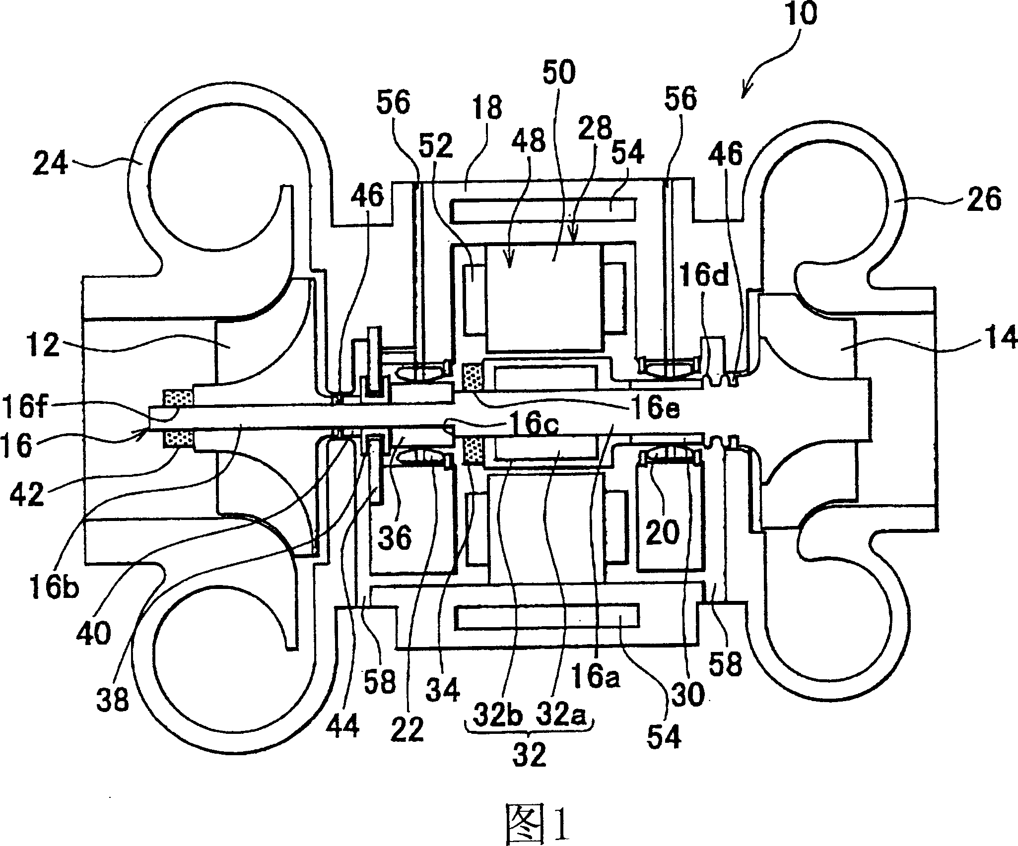
[0014] As shown in FIG. 1 , a turbocharger 10 according to one embodiment includes a connecting shaft 16 connecting a compressor wheel 12 and a turbine wheel 14 . The connecting shaft 16 is rotatably supported by bearings 20 and 22 in a center housing 18 located at the center of the turbocharger 10 .

[0015] The compressor wheel 12 is disposed in a compressor housing 24 adjacent one side of the center housing 18 and the turbine wheel 14 is disposed in a turbine housing adjacent the other side of the center housing 18 26 in. The turbocharger 10 according to the embodiment includes an electric motor 28 disposed in the center housing 18 . The electric motor 28 can positively drive the compressor wheel 12 .

[0016] The connecting shaft 16 includes a large-diameter portion 16a and a small-diameter portion 16b whose diameter is smaller than that of the large-diameter portion 16a. The turbine wheel 14 is fixed to one end of the large diameter portion 16a by welding or the like. ...


PUM


Abstract

The turbocharger has a connecting shaft (16) connecting a compressor wheel (12) and a turbine wheel (14). The shaft has a section of larger diameter and a section of smaller diameter, and intermediate units are provided between the compressor wheel and the turbine wheel. The compressor wheel is fixed to the section of smaller diameter by using a smaller screw (42) nut with respect to a flat section. A rotor (32) of an electric motor (28) is fixed to the section of the larger diameter by using a larger screw nut (34) with respect to an end section of the shaft.

Description

technical field [0001] The invention relates to a turbocharger, in particular a turbocharger with an electric motor, wherein a compressor wheel is driven by the electric motor. Background technique [0002] For example, Japanese Utility Model Application Publication No. JP-U-H3-13431 discloses a turbocharger with an electric motor, wherein a compressor wheel of the turbocharger is driven by the electric motor. The turbocharger includes a connecting shaft connecting the compressor wheel with a turbine wheel of the turbocharger. The turbine wheel is fixed at one end of the connecting shaft. When assembling such a turbocharger, first place the rotor of the electric motor, the collar whose coefficient of linear expansion is greater than that of the connecting shaft, and the compressor wheel from the turbine wheel side on the connecting shaft in this order. Set in place. Then, the nut is tightened from the compressor wheel side, so that the components provided on the connectin...

Claims


Application Information

Patent Timeline
IPC IPC(8): F02B37/00H02K1/27
CPCF02B37/11H02K7/083F02B39/10H02K7/14Y02T10/144Y02T10/12
Inventor 北田孝佳
Owner TOYOTA JIDOSHA KK
Why Eureka
Try Eureka