Dynamo-electric machine

A motor-generator and stator technology, applied in the direction of electric components, electromechanical devices, electrical components, etc., can solve the problems of insufficient contact area, increased vibration and noise, etc., to increase the degree of fixation, reduce vibration and noise, prevent The effect of reducing the axial force

Inactive Publication Date: 2008-12-17
TOYOTA JIDOSHA KK
View PDF2 Cites 15 Cited by
  • Summary
  • Abstract
  • Description
  • Claims
  • Application Information

AI Technical Summary

Problems solved by technology

[0005] In addition, in Figure 8 In the stator 20 of the conventional motor shown, since only the placement surface 20 of the lower part of the stator 20 is placed in the housing 2, and only this part contacts and is fixed to the housing, there is a problem that, Insufficient contact area between housing 2 and stator 1, increased vibration and noise

Method used


Image

  • Dynamo-electric machine
  • Dynamo-electric machine
  • Dynamo-electric machine

Examples


Embodiment Construction

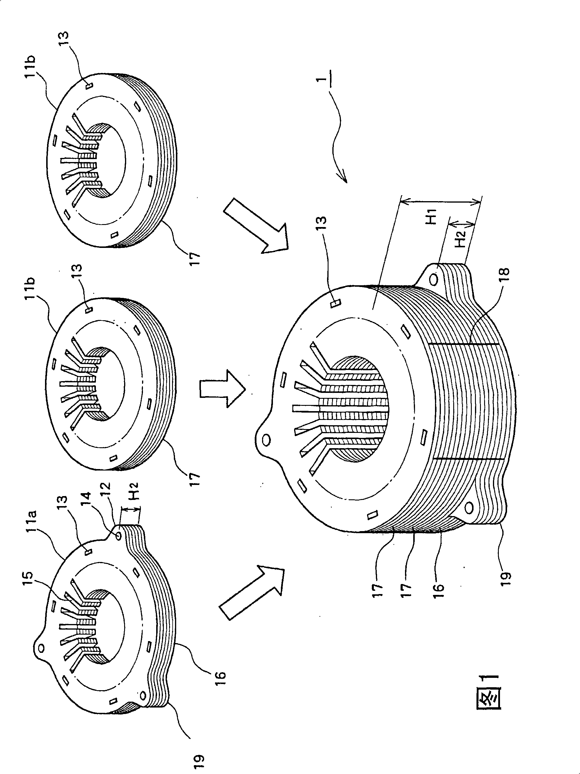
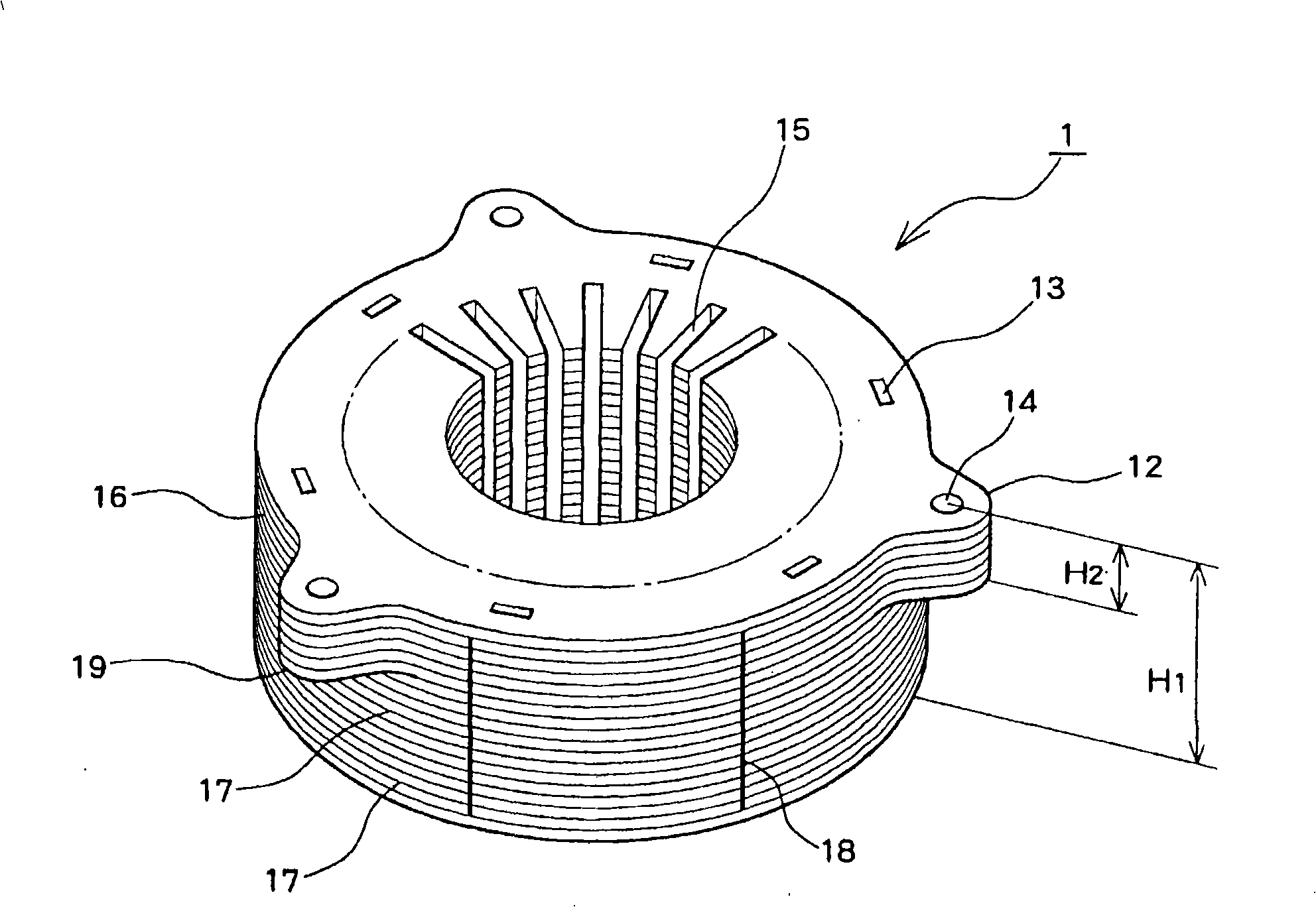
[0017] Hereinafter, embodiments of the present invention will be described in detail with reference to the drawings. 1 and 2 are schematic diagrams of a stator core 1 of a motor generator according to a first embodiment of the present invention, image 3 and 4 is an explanatory diagram of a stator core 1 of an electric motor according to a second embodiment of the present invention, and FIGS. 5 and 6 are schematic views of a stator core 1 of an electric motor according to a third embodiment of the present invention.

[0018] Fig. 1 is a perspective view of a method of manufacturing a stator core 1 in a first embodiment of the present invention. The stator core 1 is constituted by a first lamination block 16 having protrusions 12 in which bolt holes 14 are formed, and a second lamination block 17 having no protrusions 12 . Similar to the prior art described above, the first laminated block 16 is manufactured by punching a fixed-sized electromagnetic steel sheet into the shape...


PUM


Abstract

A first laminate layer block having a bolt fixing unit laminated / fixed by caulking a plurality of steel plates having lug metals protruding diametrically and a second laminate layer block laminated / fixed by caulking a plurality of steel plates not having lug metals are rolled and laminate on part of a steel plate, and are welded on the surfaces of their side surface in a laminate direction to be laminated and integrated. Accordingly, it is possible to prevent the axial force of the fixed bolt from being lowered due to thermal shock of a stator to decrease the occurrence of vibration or noise, and reduce vibration or noise by increasing the fixing levels of the stator and a case.

Description

technical field [0001] The present invention relates to a stator structure for a motor generator. Background technique [0002] In recent years, hybrid vehicles in which an engine and an electric motor are combined have been mass-produced. Drive motors installed in such hybrid vehicles such as Figure 8 What is shown generally consists of a stator 20 that generates a magnetic field, a rotor 3 that takes an output, and a housing 2 that accommodates the stator 20 and the rotor 3 . like Figure 7 As shown, the stator core 1 of the stator 20 of the motor is formed by laminating a plurality of electromagnetic steel sheets in order to reduce an induced current caused by a magnetic field passing through the stator core 1 . [0003] For example, as described in Japanese Patent Publication JP-A-2005-137057 and JP-A-6-245415, the stator 20 is manufactured as follows. First, a fixed-sized electromagnetic steel sheet is punched into the shape of the stator core 1, including the protr...

Claims


Application Information

Patent Timeline
Patent Type & Authority Applications(China)
IPC IPC(8): H02K1/18
CPCH02K1/185Y10T29/49009
Inventor 佐野新也相原浩泷泽敬次
Owner TOYOTA JIDOSHA KK
Why Eureka
Try Eureka