Robot, control device and method of controlling robot
A technology of robots and mechanical arms, applied in the field of robots and control devices, can solve the problems of the decrease of detection accuracy of force sensors and other problems
- Summary
- Abstract
- Description
- Claims
- Application Information
AI Technical Summary
Problems solved by technology
Method used
Image


Examples
no. 1 approach
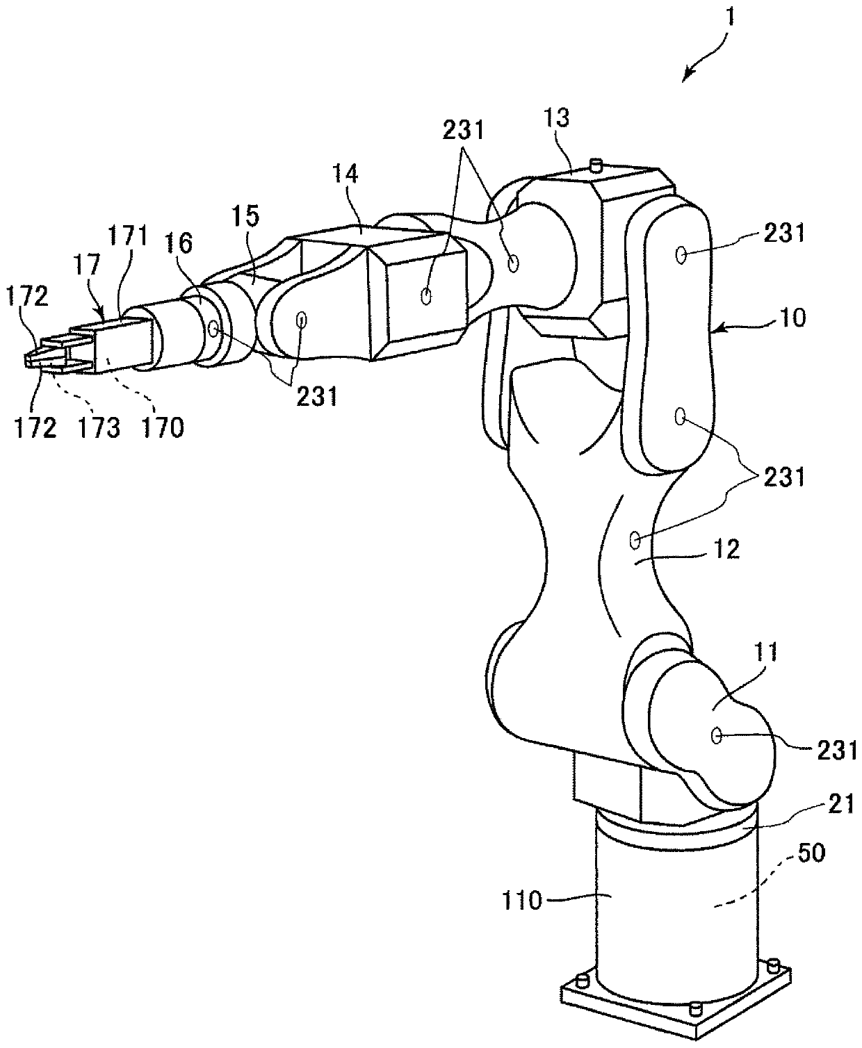
[0026] figure 1 It is a perspective view showing the robot according to the first embodiment of the present invention. figure 2 for figure 1 The block diagram of the robot is shown. In addition, hereinafter, the base 110 side of the robot 1 is referred to as a "proximal end side", and the opposite side (the end effector 17 side) is referred to as a "tip end side".
[0027] figure 1 The illustrated robot 1 is a system capable of performing operations such as material supply, material removal, transport, and assembly of precision instruments or components (objects) constituting the precision instruments, using a robot arm 10 equipped with an end effector 17 . The robot 1 includes: a robot arm 10 having a plurality of arms 11 to 16; an end effector 17 mounted on the end side of the robot arm 10; and a control device 50 for controlling the above robot arm 10 and the end effector 17. action. Hereinafter, first, the outline of the robot 1 will be described.
[0028] The robot...
no. 2 approach
[0090] Figure 7It is a perspective view showing the robot according to the second embodiment of the present invention. Figure 8 for Figure 7 The block diagram of the robot is shown. Figure 9 show Figure 7 A diagram showing an example of a surveillance area D where the proximity sensor 231 is used to detect the presence of an object.
[0091] Hereinafter, in the second embodiment, the difference from the above-mentioned embodiment will be mainly described, and the description of the same matters will be omitted. In addition, in Figure 7 to Figure 9 In , the same symbols are assigned to the same configuration as in the first embodiment described above.
[0092] Figure 7 and Figure 8 The shown robot 1' includes a proximity sensor 232 (sensor unit) provided on the end effector 17 in addition to the proximity sensor 231 provided on the robot arm 10. As this proximity sensor 232, the same sensor as the proximity sensor 231 mentioned above can be used. That is, the p...
no. 3 approach
[0106] Figure 10 It is a perspective view showing the robot according to the third embodiment of the present invention.
[0107] Hereinafter, in the third embodiment, the difference from the above-mentioned embodiment will be mainly described, and the description of the same matters will be omitted. In addition, in Figure 10 In , the same symbols are assigned to the same configuration as in the first embodiment described above.
[0108] in the aforementioned figure 1 In the shown robot 1, the force sensor 21 is provided closer to the base end side than the robot arm 10. In contrast, in the Figure 10 In the illustrated robot 1A, the force sensor 21 is provided closer to the tip side than the robot arm 10 . That is to say, Figure 10 The illustrated force sensor 21 is disposed between the robot arm 10 and the end effector 17 .
[0109] By disposing the force sensor 21 at the position described above, the force sensor 21 can efficiently detect an external force applied t...
PUM
 Abstract
Description
Claims
Application Information