
Door cover damping device, door cover assembly and washing machine

A damping device and door cover technology, applied in the field of washing machines, can solve the problems of increasing the structural complexity and volume of the door cover damping device, difficulty in taking into account product experience and safety, and deviate from the perspective design of the door cover, etc., to achieve the appearance width Simplified size, improved user experience, and solved the effect of obstructed vision

Active Publication Date: 2019-12-13
WUXI LITTLE SWAN ELECTRIC CO LTD
View PDF8 Cites 0 Cited by
  • Summary
  • Abstract
  • Description
  • Claims
  • Application Information

AI Technical Summary

Problems solved by technology

For example, the minimum closing angle of the door cover damping device is the most critical performance. In order to improve this performance, a linear damper has been used in the new scheme to improve the minimum damping angle to about 10 degrees. However, it has been found in practice that this situation The structural complexity and volume of the door cover damping device will be correspondingly increased. For example, in the existing scheme of arranging lever transmission structures side by side at the side of the linear damper, although the minimum damping angle can be improved, the entire door cover damping device The large size will block the see-through part of the door cover to a large extent, seriously affecting the see-through effect of the door cover. This deviates from the original intention of the see-through design of the door cover, and it is difficult to balance product experience and safety.

Method used


Image

  • Door cover damping device, door cover assembly and washing machine
  • Door cover damping device, door cover assembly and washing machine
  • Door cover damping device, door cover assembly and washing machine

Examples


Embodiment Construction

[0049] In order to understand the above-mentioned purpose, features and advantages of the present invention more clearly, the present invention will be further described in detail below in conjunction with the accompanying drawings and specific embodiments. It should be noted that, in the case of no conflict, the embodiments of the present application and the features in the embodiments can be combined with each other.

[0050] In the following description, many specific details are set forth in order to fully understand the present invention. However, the present invention can also be implemented in other ways different from those described here. Therefore, the protection scope of the present invention is not limited by the specific details disclosed below. EXAMPLE LIMITATIONS.

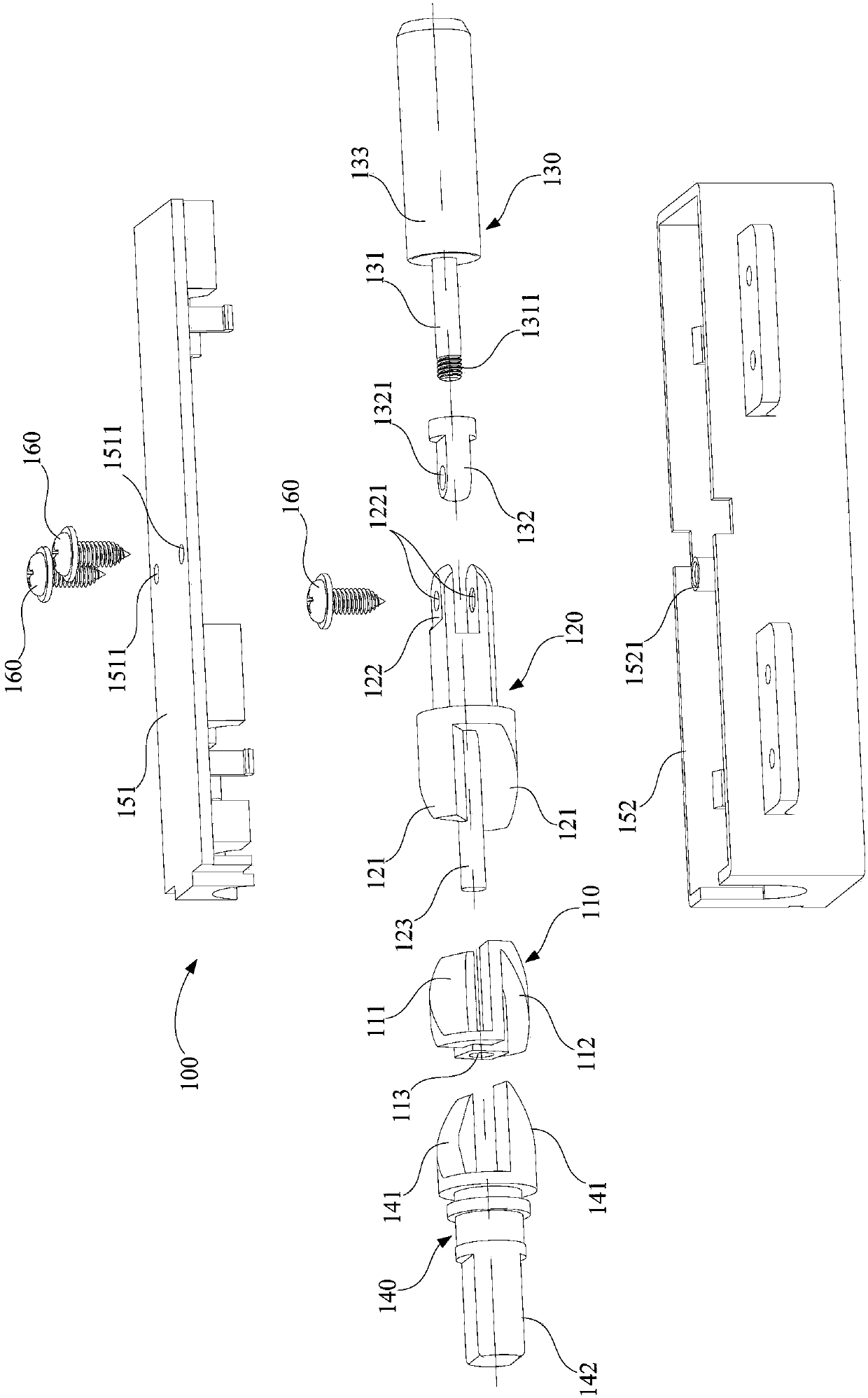
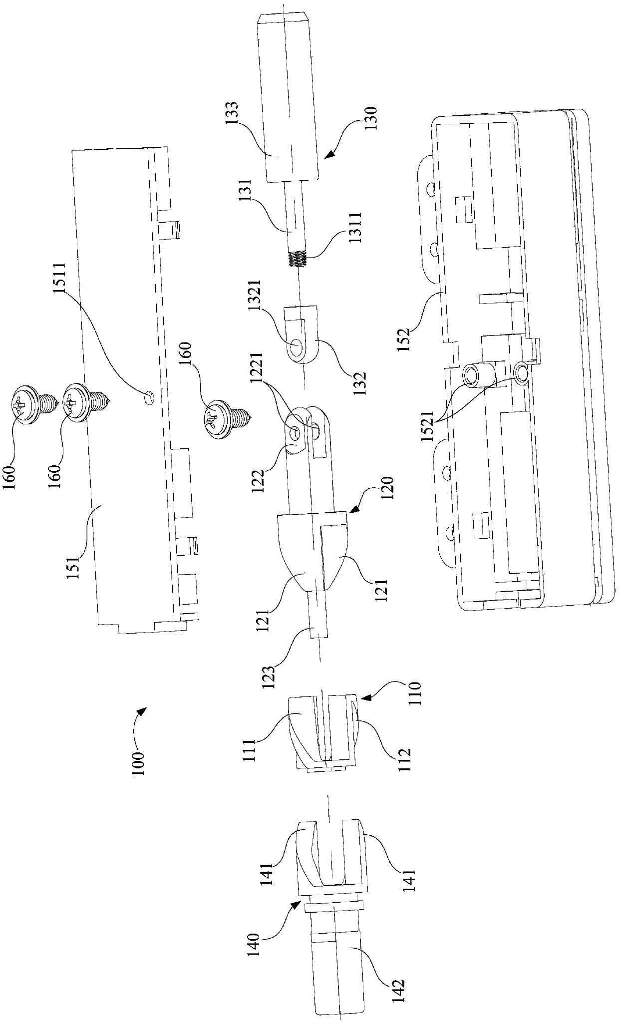
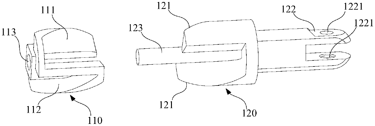
[0051] Refer below Figure 1 to Figure 3 The door cover damping device, door cover assembly and washing machine according to some embodiments of the present invention are described.

[0052] Such a...


PUM


Abstract

The invention provides a door cover damping device, a door cover assembly and a washing machine. The door cover damping device comprises a transmission assembly and a linear damper, wherein the transmission assembly comprises a rotary part and a movable part; when the rotary part rotates, the movable part is driven by a transmission structure to axially and linearly move in the axial direction ofthe rotary part; the linear damper is located on one side of the axial direction of the rotary part and linearly moves between the linear damper and the rotary part; when the movable part moves underdriving of the rotary part, the linear damper can be triggered; when the linear damper is triggered, a pushing force is applied to the movable part, and when the movable part is pushed by the pushingforce, the transmission structure transmits torque which prevents the rotary part from continuing to rotate. According to the door cover damping device, the linear damper, the rotary part and the movable part form series assembly which is generally arranged along a straight line in an arrangement mode, the width of a product is small, the compression stroke of the transmission assembly on the linear damper is large, and the purpose of improving both the use experience and safety of equipment can be achieved.

Description

technical field [0001] The invention relates to the field of washing machines, in particular to a door cover damping device, a door cover assembly and a washing machine. Background technique [0002] With the increasing demand for large-capacity and high-end washing machines and other equipment, the door covers of existing washing machines, especially fully automatic washing machines, are becoming larger and larger. Generally, high-end equipment is used to facilitate consumers to observe the internal operation status of the equipment. A see-through glass door cover will be used. Obviously, the door cover of this high-capacity high-end device will become heavier and heavier. At the same time, the user will have a greater risk of pinching his hand when opening and closing the door cover. [0003] In order to improve the safety of consumers, such devices as washing machines are generally equipped with door cover damping devices. The minimum angle of the damping force generated ...

Claims


Application Information

Patent Timeline
Patent Type & Authority Applications(China)
IPC IPC(8): D06F39/14D06F37/42
CPCD06F39/14D06F37/42
Inventor 朴锺相
Owner WUXI LITTLE SWAN ELECTRIC CO LTD
Learn More