Silicon pole plate and preparation method thereof

A technology of polar plates and silicon wafers, applied in the field of silicon materials, can solve problems such as large volume, cumbersome production, and low strength

Active Publication Date: 2019-12-17
SUNLAND SHANGHAI INVESTMENT CO LTD
View PDF11 Cites 4 Cited by
  • Summary
  • Abstract
  • Description
  • Claims
  • Application Information

AI Technical Summary

Problems solved by technology

[0005] In the prior art, the types of bipolar plates of fuel cells mainly include graphite plates or metal plates, wherein graphite plates are mainly obtained by pressing carbon powder or graphite powder mixed with graphitizable resin, which mainly has large volume and low power density. And the disadvantage of low strength; metal plates are generally directly processed by stainless steel, titanium alloy, aluminum alloy, etc., which mainly have the defect of being easily corroded, and generally require various surface modifications, which in turn leads to complex preparatio...

Method used


Image

  • Silicon pole plate and preparation method thereof
  • Silicon pole plate and preparation method thereof
  • Silicon pole plate and preparation method thereof

Examples


Embodiment 1

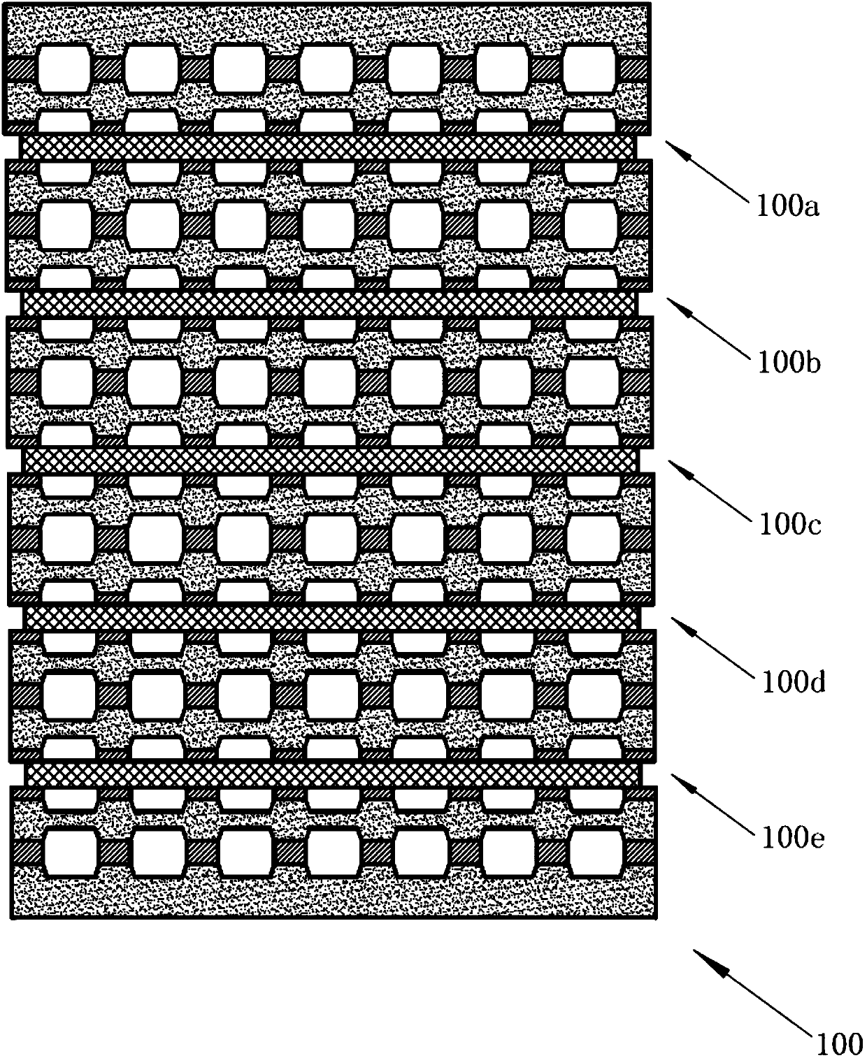
[0062] See figure 1 A fuel cell stack structure 100 is shown. The stack structure 100 includes fuel cell units connected in series and stacked together, and the number is not less than three. Specifically, in this embodiment, the number of fuel cell units 5; preferably, the output power of the electric stack structure 100 is not less than 0.1KW, of course, in other embodiments of the present invention, those skilled in the art can completely according to the required power requirements of the product field that actually needs to be applied, to select the number of fuel cell units, which is not specifically limited in the present invention.

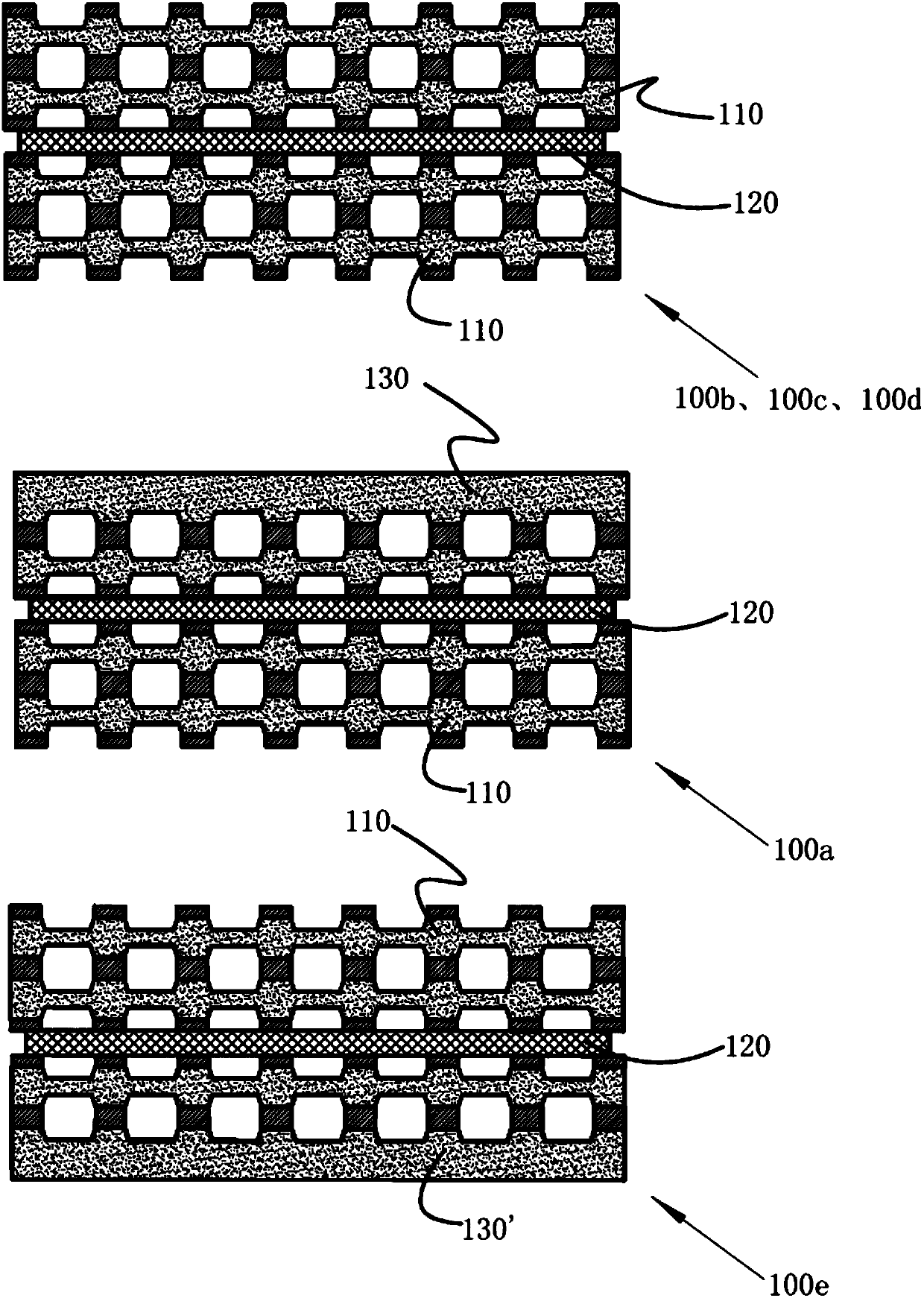
[0063] Such as figure 1 As shown, the stack structure of this embodiment 1 includes end fuel cell units 100a, 100e located at both ends and three middle fuel cell units 100b, 100c, 100d located in the middle, and each fuel cell unit includes sequentially stacked as a whole The anode plate, the anode electrode, the electrolyte diaphragm, ...

Embodiment 2

[0102] The rest of the technical solutions of this embodiment 2 are the same as those of embodiment 1, the difference is that in this embodiment 2, the silicon wafer adopts phosphorus-doped or boron-doped single crystal or polycrystalline silicon wafer, preferably, the resistivity range of the silicon wafer is 0.0005-0.05Ω.cm; see Figure 6 As shown, the preparation method of the middle silicon pole plate 210 includes the following steps:

[0103] B10), preparing the first silicon wafer and the second silicon wafer;

[0104] B20), respectively fabricating the first internal cooling medium channel on the reverse side, the reducing agent channel 211 on the front side, and the first inlet and outlet combination on both sides of the first silicon wafer by laser technology, and fabricating respectively on both sides of the second silicon wafer The combination of the second internal cooling medium channel on the front side, the oxidant channel 213 on the back side, and the second i...

Embodiment 3

[0109] The rest of the technical solutions of this embodiment 3 are the same as those of embodiment 1, the difference is that in this embodiment 3, the silicon chip is a single crystal or polycrystalline silicon chip doped with phosphorus or boron, preferably, the resistivity range of the silicon chip is 0.0005-0.05Ω.cm; see Figure 7 As shown, the preparation method of the middle silicon pole plate 310 includes the following steps:

[0110] C10), preparing the first silicon wafer and the second silicon wafer;

[0111] C20), directly using screen printing process (also called positive plastic process) to make conductive material layer 316 on both sides of the first silicon chip and the second silicon chip respectively, through the formation of conductive material layer 316, and then the first silicon The sheet can directly form the first inner cooling medium flow channel on the reverse side and the reducing agent flow channel 311 on the front side, and the second silicon chip...


PUM

PropertyMeasurementUnit
Resistivityaaaaaaaaaa
Thicknessaaaaaaaaaa
Sizeaaaaaaaaaa

Abstract

The invention discloses a silicon pole plate and a preparation method thereof. The silicon pole plate is made of a doped conductive crystalline silicon material and is provided with an internal cooling medium flow channel, a front reducing agent flow channel and/or a back oxidizing agent flow channel, wherein the internal cooling medium flow channel, the front reducing agent flow channel and/or the back oxidizing agent flow channel are/is respectively provided with a silicon pole plate inlet and outlet combination communicated with the internal cooling medium flow channel, the front reducing agent flow channel and/or the back oxidizing agent flow channel. Compared with a metal pole plate, a graphite pole plate or a composite material pole plate in the prior art, the silicon pole plate provided by the invention has better advantages in the aspects of service life, cost, efficiency and power density, and undoubtedly has great significance and a core promotion effect on the large-batch industrialization process of fuel cells.

Description

technical field [0001] The invention belongs to the field of silicon materials, and in particular relates to a silicon pole plate, and also relates to a preparation method of the silicon pole plate. Background technique [0002] A fuel cell is a chemical device that directly converts the chemical energy of fuel into electrical energy, also known as an electrochemical generator. Since the fuel cell converts the Gibbs free energy in the chemical energy of the fuel into electrical energy through an electrochemical reaction, it is not limited by the Carnot cycle effect, and the energy conversion rate is high; and the reaction product of the fuel cell using hydrogen as fuel is Water, environmentally friendly, theoretically can achieve zero pollution emissions; in addition, the fuel cell has no mechanical transmission parts, less moving parts, and low noise during operation; moreover, the fuel cell also has high specific energy, high reliability, wide fuel range, and easy to start...

Claims


Application Information

Patent Timeline
IPC IPC(8): H01M8/0258H01M8/0267H01M8/0232
CPCH01M8/0232H01M8/0258H01M8/0267Y02E60/50
Inventor 朱景兵施正荣
Owner SUNLAND SHANGHAI INVESTMENT CO LTD
Why Eureka
Try Eureka