Water inlet channel interception device for hydroelectric power generation equipment

A technology of power generation equipment and interception devices, which is applied in water conservancy projects, cleaning of open water surfaces, construction, etc., can solve the problems of grid blockage, insufficient water intake of generator sets, etc., and achieve the effects of easy cleaning, simple structure, and convenient layout

Active Publication Date: 2020-09-22
永康市能泽科技有限公司
View PDF5 Cites 0 Cited by
  • Summary
  • Abstract
  • Description
  • Claims
  • Application Information

AI Technical Summary

Problems solved by technology

[0003] However, we have found in actual operation that the floating objects in the water will be drawn into the generator set. The existing treatment method is to install a grille at the water inlet position of the generator set, and intercept the floating objects through the grille , but the grid mesh is often blocked, resulting in insufficient water intake in the generator set

Method used


Image

  • Water inlet channel interception device for hydroelectric power generation equipment
  • Water inlet channel interception device for hydroelectric power generation equipment
  • Water inlet channel interception device for hydroelectric power generation equipment

Examples


Embodiment 1

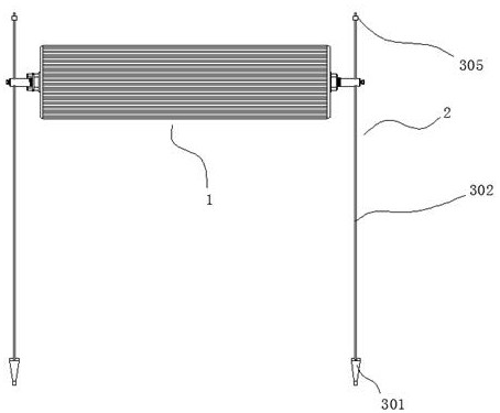
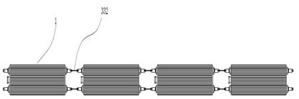
[0042] refer to Figure 1 to Figure 6 As shown, a water conservancy power generation equipment inlet channel interception device shown includes a floating device 1, and a tightening device 2 for tightening the floating device 1;

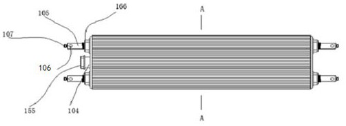
[0043]The floating device 1 includes a floating bucket 101, a cavity 102 is formed inside the floating bucket 101, and a nozzle 104 communicating with the cavity 102 is formed at one end of the floating bucket 101 by injection molding. An end cap 155 is threadedly connected to the nozzle 104, and a pipe hole 103 is formed by injection molding at the end face of the buoyant bucket 101, the pipe hole 103 runs through the buoyant bucket 101 transversely, and a rod is inserted in the pipe hole 103 105, the two ends of the rod 105 extend to the outside of the buoy 101 and then are equipped with nuts 166, the nuts 166 are screwed in and contact the buoy 101, and the outer walls of the rod 105 near both ends are A through hole 106 is processed, the through...

Embodiment 2

[0048] refer to Figure 7 As shown, a protective layer 110 is sandwiched between the buoy 101 and the shell 108; the main function of the protective layer 110 is to place the buoy to leak after being tiled. When we install the fixing device, the fixing device is If it is pierced into the shell, it may puncture the floating bucket when the force is excessive, but by setting a protective layer, the puncture can be effectively avoided; at the same time, the protective layer can also increase the rigidity of the product. The shell is soft and can absorb Collision force, the protective layer can increase the bending strength and reduce the chance of the buoy being damaged.

[0049] The protective layer 110 is made of stainless steel with a thickness of 0.25mm~0.55mm.

Embodiment 3

[0051] refer to Figure 8 and Figure 9 As shown, the fixing device 7 includes a cannula 701, one end of the cannula 701 is processed into a conical piercing end 711, and the bristles 4 are inserted into the cannula 701 and fixed by spot welding. The side of the housing 108 is axially provided with a first through hole 5, and a plurality of positioning grooves 6 corresponding to the first through holes 5 are annularly provided on the outer wall of the housing 108, and the positioning grooves 6 axially penetrate all The casing 108, the piercing end 711 pierces from the positioning groove 6, and pierces into the first through hole 5; the fixing device is easy to process, and it is easy to fit in when assembling. At first, the cannula can be preheated. The preheated cannula can be inserted into the shell more easily, and it will cause the heat fusion of the shell. When the heat-fused part of the shell is cooled again, it can be effectively Clamp and fix the cannula to prevent t...


PUM


Abstract

The invention discloses a hydraulic power generation equipment water feeding channel intercepting device. The hydraulic power generation equipment water feeding channel intercepting device comprises afloating device and tightening devices used for tightening the floating device; the floating device comprises a floating barrel, a cavity is formed in the floating barrel, a pipe opening communicating with the cavity is formed at one end of the floating barrel through injection molding, and an end cover is in threaded connection with the pipe opening; pipe holes are formed in the end surface of the floating barrel through injection molding and transversely penetrate through the floating barrel; a rod piece is inserted into each pipe hole in a penetrating mode, the two ends of the rod piece are provided with nuts after extending to the outside of the floating barrel, and the nuts make contact with the floating barrel after being screwed; and the positions, close to the two end surfaces, ofthe outer walls of the rod pieces are provided with through holes through machining. The hydraulic power generation equipment water feeding channel intercepting device can cooperate with a grille netfor protection, so that water entering a water feeding channel is intercepted, and the quantity of seston entering a power generator unit is effectively decreased.

Description

technical field [0001] The invention relates to an intercepting device for a water inlet channel of a water conservancy power generation equipment. Background technique [0002] Hydropower is a way of generating electricity, and the water energy used is mainly the potential energy stored in the water body. It uses buildings to concentrate the drop of natural water flow to form a water head, and collects and regulates the flow of natural water flow with a reservoir; the basic equipment is a hydroelectric generator set. When the water flows through the water turbine, the water turbine is driven by the water flow to rotate, and the water turbine drives the generator to generate electricity. The mechanical energy is converted into electrical energy, and then the electricity is sent to the user through power transformation and power transmission and distribution equipment. Water energy is a renewable energy source in nature, and it is regenerated repeatedly along with the hydrol...

Claims


Application Information

Patent Timeline
Patent Type & Authority Patents(China)
IPC IPC(8): E02B15/06
CPCE02B15/06
Inventor 方文珠张开良吕晓宁
Owner 永康市能泽科技有限公司
Why Eureka
Try Eureka