Robot with wheel-leg structure and control method thereof

A control method and robot technology, applied in the field of robots, can solve problems such as complex structure and instability, and achieve the effect of improving safety, good adaptability and improving operation efficiency.

Active Publication Date: 2022-07-29
SOUTHWEAT UNIV OF SCI & TECH
View PDF18 Cites 0 Cited by
  • Summary
  • Abstract
  • Description
  • Claims
  • Application Information

AI Technical Summary

Problems solved by technology

[0005] The object of the present invention is: the present invention provides a robot with a wheel-leg structure and its control method, which solves the problem of complex and unstable structures of existing wheel-leg robots

Method used


Image

  • Robot with wheel-leg structure and control method thereof
  • Robot with wheel-leg structure and control method thereof
  • Robot with wheel-leg structure and control method thereof

Examples


Embodiment 1

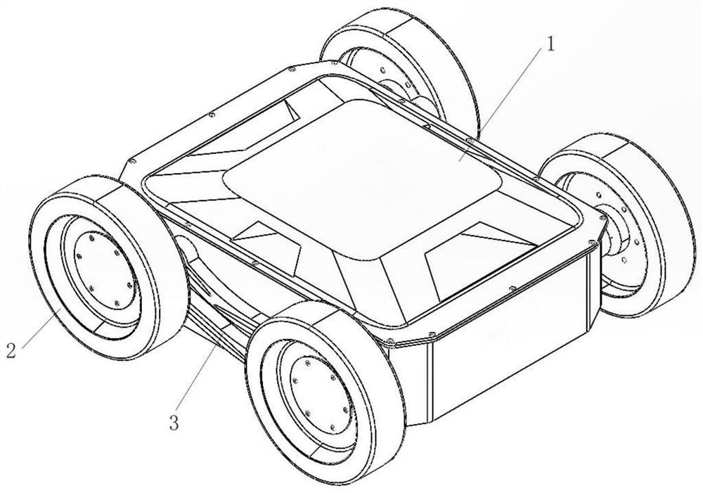
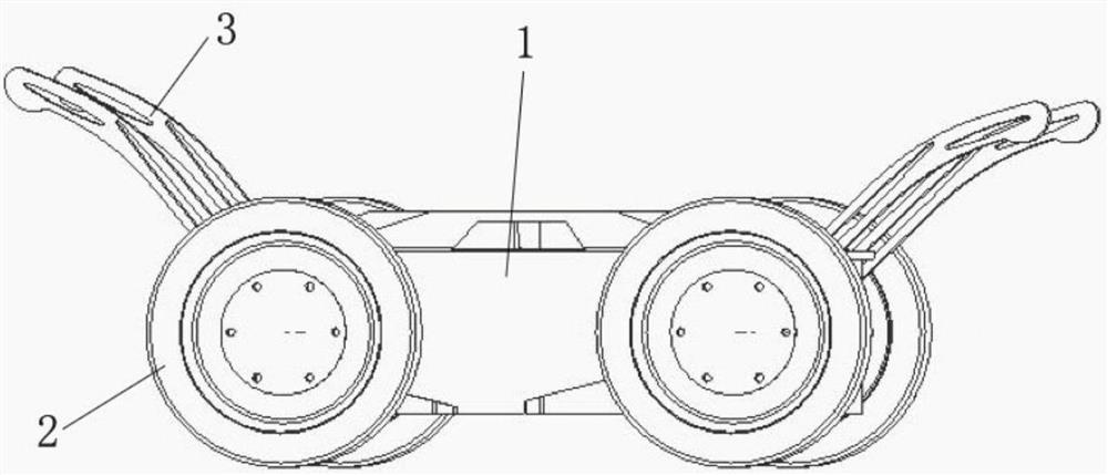
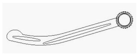
[0041] refer to Figure 1 to Figure 6 As shown, a robot with wheel and leg structure includes a body 1, a wheel 2, a mechanical leg 3, a connecting shaft 4, an independent drive mechanism, a clutch 7, an axial telescopic mechanism and a sleeve rod 10, and the independent drive mechanism includes a drive motor 5 , the axial telescopic mechanism includes a telescopic motor 8 and a telescopic push rod 9 , the clutch 7 includes a solenoid valve 6 , an inner contact plate 11 and an outer contact plate 12 .

[0042] The fuselage 1 is a rectangular box-shaped structure. The top of the fuselage 1 has openings in four directions: front, rear, left, and right. Cameras can be installed inside to collect visual information in four directions at the same time.

[0043] The four corners of the fuselage 1 correspond to four sets of wheels 2, mechanical legs 3, connecting shafts 4, independent drive mechanisms, clutches 7 and sleeve rods 10, and the front and rear of the fuselage 1 correspond...

Embodiment 2

[0055] refer to Figure 1 to Figure 7 As shown, a control method of the robot with the above-mentioned wheel-leg structure, when the robot is running normally, the connecting shaft 4 and the wheel 2 are driven to move by an independent driving mechanism, at this time the clutch 7 is disengaged, and the mechanical leg 3 is in a retracted state, parallel to the Both sides of the fuselage 1 do not rotate with the connecting shaft 4 .

[0056] When the robot encounters an obstacle that is difficult to cross, the control clutch 7 is closed. At this time, the mechanical leg 3 rotates together with the connecting shaft 4 to realize the rotating motion of the mechanical leg 3. Through the cooperation of each mechanical leg 3 and the wheel 2, the obstacle is completed. Behavior.

[0057] Due to the limited internal space of the robot and the limited resource allocation, the various parts of the robot are prone to failure in a nuclear emergency environment. Flow chart such as Figure...


PUM


Abstract

The invention discloses a robot with a wheel-leg structure and a control method of the robot. The robot comprises a robot body, a rotary connecting shaft is arranged on the robot body and connected with wheels, a rotary sleeve rod is arranged on the robot body, a clutch is arranged between the connecting shaft and the sleeve rod, and the sleeve rod is connected with mechanical legs. In the control method, when the robot runs normally, the independent driving mechanism drives the connecting shaft and the wheels to move; when the robot encounters an obstacle difficult to cross, the clutch is controlled to be closed, at the moment, the mechanical legs rotate along with the connecting shafts, rotating motion of the mechanical legs is achieved, and the obstacle crossing behavior is completed through cooperation of the mechanical legs and the wheels. The robot has the beneficial effects that when facing an obstacle, the robot crosses the obstacle through cooperative operation of the leg structure and the wheels; when the gravity center of the vehicle shifts and the vehicle body is clamped or rolls over, a normal driving posture is recovered in time by adjusting a telescopic push rod of the supporting mechanism; and when on a relatively flat road surface, the wheels are used for realizing high-speed running, so that the working efficiency is improved.

Description

technical field [0001] The invention belongs to the technical field of robots, in particular to a robot with a wheel-leg structure and a control method thereof. Background technique [0002] With the development of science and technology, robots are playing an increasingly important role in various fields. At present, common robots for complex terrain operations include wheeled robots, crawler robots, and legged robots. Among them, wheeled robots have the advantages of high speed, high efficiency, and low motion noise. However, it has poor ability to overcome obstacles, poor terrain adaptability, and large turning radius, making it difficult to operate in complex environments. Compared with wheeled robots, crawler robots have stronger ability to overcome obstacles, stronger terrain adaptability, and can turn on the spot. But the speed is slow, the efficiency is low, and the motion noise is too loud. The legged robot has strong adaptability to the terrain, the legs have m...

Claims


Application Information

Patent Timeline
Patent Type & Authority Applications(China)
IPC IPC(8): B62D57/028
CPCB62D57/028
Inventor 王坤朋杨文昊姚娟张瑞李文博刘切
Owner SOUTHWEAT UNIV OF SCI & TECH
Why Eureka
Try Eureka