Photomask blank

Active Publication Date: 2007-10-25
SHIN ETSU CHEM IND CO LTD +1
View PDF3 Cites 39 Cited by
  • Summary
  • Abstract
  • Description
  • Claims
  • Application Information

AI Technical Summary

Benefits of technology

[0014]It is therefore an object of the present invention to provide a photomask blank with substantially problem-free chemical stability in a transition metal silicide having a silicon content, expressed as silicon/(silicon+transition metal), of less than 80 atom %. Such a transition metal silicide, although previously thought to be difficult to u

Problems solved by technology

However, this does not mean that the need for accuracy can be relaxed accordingly.
In some cases, the resist pattern may even collapse or separate from the substrate.
As a result, when such etching is carried out using a thin resist film, it is difficult to accurately transfer the resist pattern.
How to require of a resist that it have an etch resistance which enables etching to be carried out to a high resolution and to a high accuracy h

Method used


Image

  • Photomask blank
  • Photomask blank
  • Photomask blank

Examples


examples

[0075]The Experiments and Examples below are given by way of illustration and not by way of limitation.

Experiments 1 to 15

[0076]Sputtering was carried out using separate molybdenum and silicon targets in an argon atmosphere or an atmosphere of argon gas and nitrogen gas while adjusting the applied power, thereby depositing the MoSi-based material films 1 to 15 (film thickness, 39 nm) shown in Table 1 onto a transparent substrate made of quartz. The film was then immersed for one hour in an ammonia-peroxide mixture (ammonia water / aqueous hydrogen peroxide / water=1:1:30 by volume), and the change (decrease) in film thickness was measured. The change in film thickness and the optical density of each film is indicated in the table below. At a nitrogen content below 5 atom %, the film lacked a sufficient chemical resistance, whereas at a nitrogen content above 40 atom %, the optical density was low, making the film unsuitable for use as a light-shielding film. It was confirmed that at a n...

example 6

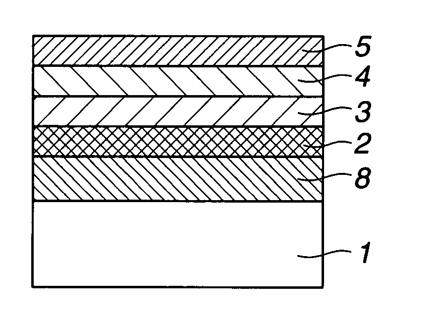
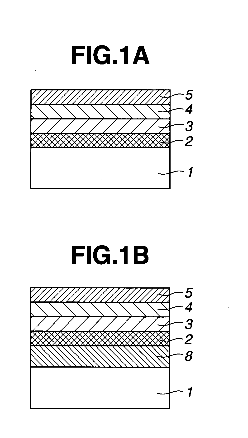
[0079]A photomask blank having the film construction shown in FIG. 1A was produced by using sputtering processes to deposit the respective films. The individual films were as follows.[0080]Transparent substrate: Quartz substrate[0081]Etching stopper film: CrN (CR:N=9:1 (atomic ratio); film thickness, 10 nm)[0082]Light-shielding film: MoSiN (Mo:Si:N=1:3:1.5 (atomic ratio); film thickness, 41 nm)[0083]Antireflective film: MoSiN (the composition was graduated in the thickness direction, being Mo:Si:N=1:3:1.5 (atomic ratio) on the light-shielding film side and Mo:Si:N=1:5:5 (atomic ratio) on the side away from the transparent substrate (etching mask film side); film thickness, 18 nm)[0084]Etching mask film: CrN (Cr:N=9:1 (atomic ratio); film thickness, 10 nm)

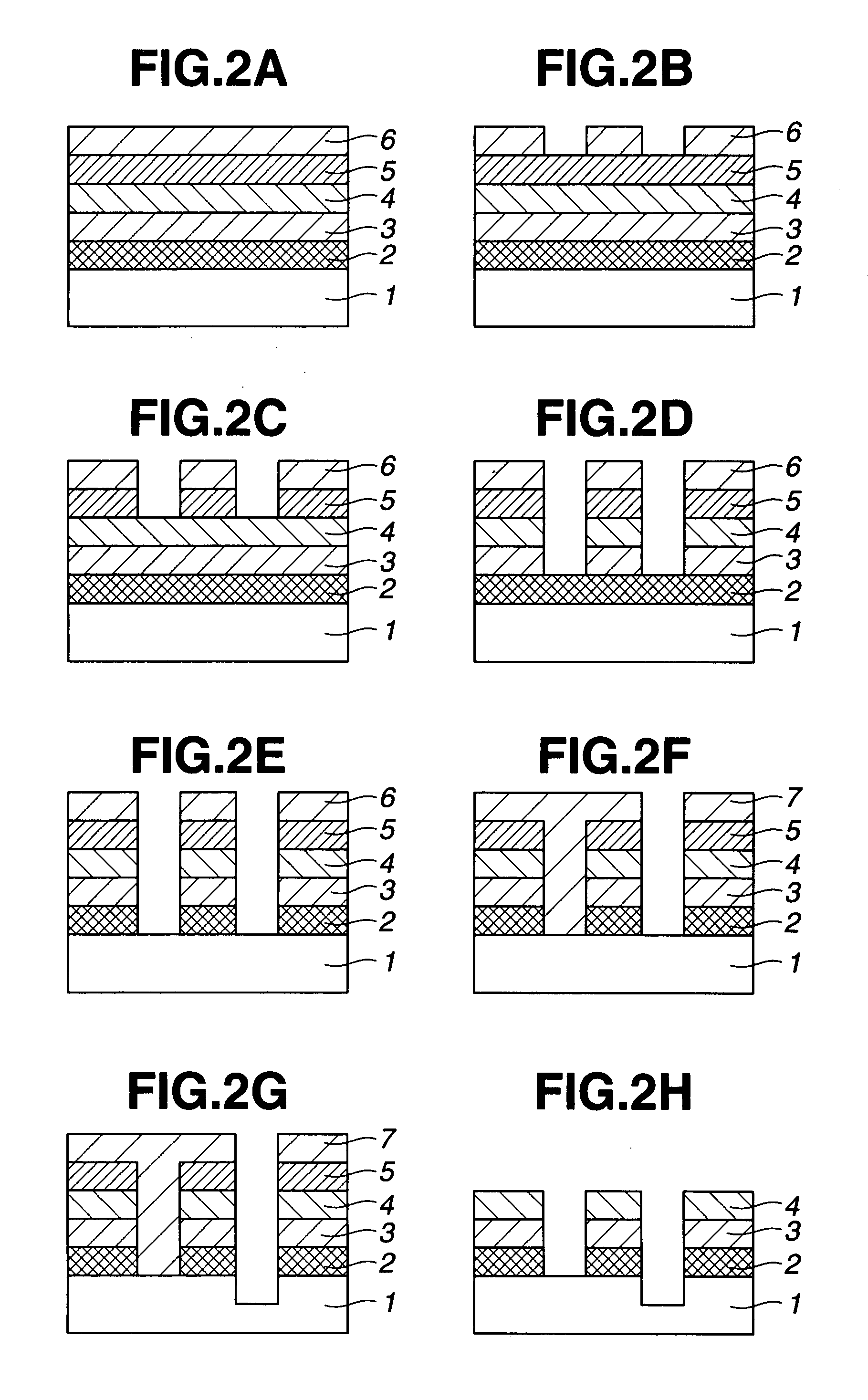
[0085]This photomask blank was processed in accordance with photomask Fabrication Example A described above, thereby producing a Levenson mask.

[0086]Chemically amplified negative resist films composed primarily of a hydroxystyrene r...

example 7

[0088]A photomask blank having the film construction shown in FIG. 1A was produced by using sputtering processes to deposit the respective films. The individual films were as follows.[0089]Transparent substrate: Quartz substrate[0090]Etching stopper film: CrN (CR:N=9:1 (atomic ratio); film thickness, 10 nm)[0091]Light-shielding film: MoSiN (Mo:Si:N=1:3:1.5 (atomic ratio); film thickness, 41 nm)[0092]Antireflective film: MoSiN (the composition was graduated in the thickness direction, being Mo:Si:N=1:3:1.5 (atomic ratio) on the light-shielding film side and Mo:Si:N=1:5:5 (atomic ratio) on the side away from the transparent substrate (etching mask film side); film thickness, 18 nm)[0093]Etching mask film: CrN (Cr:N=9:1 (atomic ratio); film thickness, 10 nm)

[0094]This photomask blank was processed in accordance with photomask Fabricating Example B described above, thereby producing a zebra-type chromeless mask.

[0095]Chemically amplified negative resist films composed primarily of a hyd...


PUM

PropertyMeasurementUnit
Fractionaaaaaaaaaa
Fractionaaaaaaaaaa
Fractionaaaaaaaaaa

Abstract

A photomask blank has a light-shielding film composed of a single layer of a material containing a transition metal, silicon and nitrogen or a plurality of layers that include at least one layer made of a material containing a transition metal, silicon and nitrogen, and has one or more chrome-based material film. The high transition metal content ensures electrical conductivity, preventing charge-up in the photomask production process, and also provides sufficient chemical stability to cleaning in photomask production. The light-shielding film has a good resistance to dry etching of the chrome-based material film in the presence of chlorine and oxygen, thus ensuring a high processing accuracy.

Description

CROSS-REFERENCE TO RELATED APPLICATION[0001]This non-provisional application claims priority under 35 U.S.C. §119(a) on Patent Application No. 2006-117327 filed in Japan on Apr. 21, 2006, the entire contents of which are hereby incorporated by reference.BACKGROUND OF THE INVENTION[0002]1. Field of the Invention[0003]The present invention relates to a photomask blank for making photomasks used in the fabrication of semiconductor integrated circuits, charge-coupled devices (CCD), color filters for liquid crystal displays (LCD), magnetic heads and the like.[0004]2. Prior Art[0005]In semiconductor fabrication, the increasing level of integration in large-scale integrated circuits in particular has led to a growing need in recent years for circuit patterns of smaller geometries. This need has intensified the desire for technology to reduce the size of features in the wiring patterns that make up a circuit and technology to reduce the size of features in contact hole patterns for the inte...

Claims


Application Information

Patent Timeline
IPC IPC(8): B32B9/00B32B17/10B32B17/06G03F1/00C23C14/06G03F1/30G03F1/32G03F1/34G03F1/54
CPCG03F1/14G03F1/58G03F1/32Y10T428/31616B32B17/06C23C14/06C23C14/0641G03F1/20G03F1/62H01L21/0274
Inventor YOSHIKAWA, HIROKIINAZUKI, YUKIOOKAZAKI, SATOSHIHARAGUCHI, TAKASHISAGA, TADASHIFUKUSHIMA, YUICHI
Owner SHIN ETSU CHEM IND CO LTD
Why Eureka
Try Eureka