

Long-span reinforced concrete inner support structure of rectangular deep foundation pit and construction method of structure
A reinforced concrete and support structure technology, which is applied in basic structure engineering, excavation, construction, etc., can solve the problems of difficulty in reaching the level of the foundation pit, vertical two-way force balance, and single support form, and achieves small deformation and convenient construction. , the effect is remarkable
- Summary
- Abstract
- Description
- Claims
- Application Information
AI Technical Summary
Problems solved by technology
Method used
Image

Examples
Embodiment 1
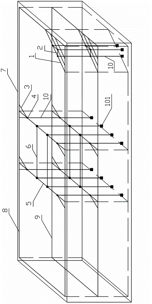
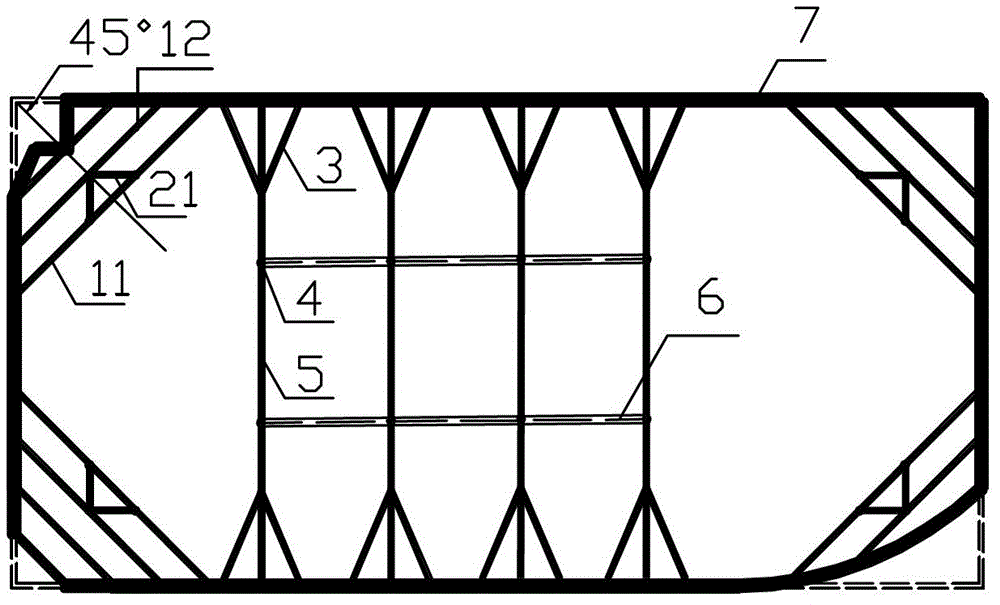
[0054] A rectangular deep foundation pit long-span reinforced concrete inner support structure, such as figure 1 As shown, the large-span reinforced concrete internal support structure of the rectangular deep foundation pit includes a soil retaining structure 7 at the edge of the foundation pit, an internal support three-dimensional support structure including a steel support column 10, and a crown beam. The crown beam is an internal support three-dimensional The internal support three-dimensional support structure described by the ring beam at the connection between the support structure and the top of the retaining structure at the side of the foundation pit has two layers, and each layer includes the corner structure of the foundation pit, the symmetrical support structure in the middle of the foundation pit, and the longitudinal support structure. Beam 6;
[0055] The corner structure of the foundation pit includes a large diagonal brace 1 located at the corner of the fou...
Embodiment 2
[0065] A construction method for a large-span reinforced concrete inner support structure of a rectangular deep foundation pit, the construction process comprising:
[0066] A. overall preparation
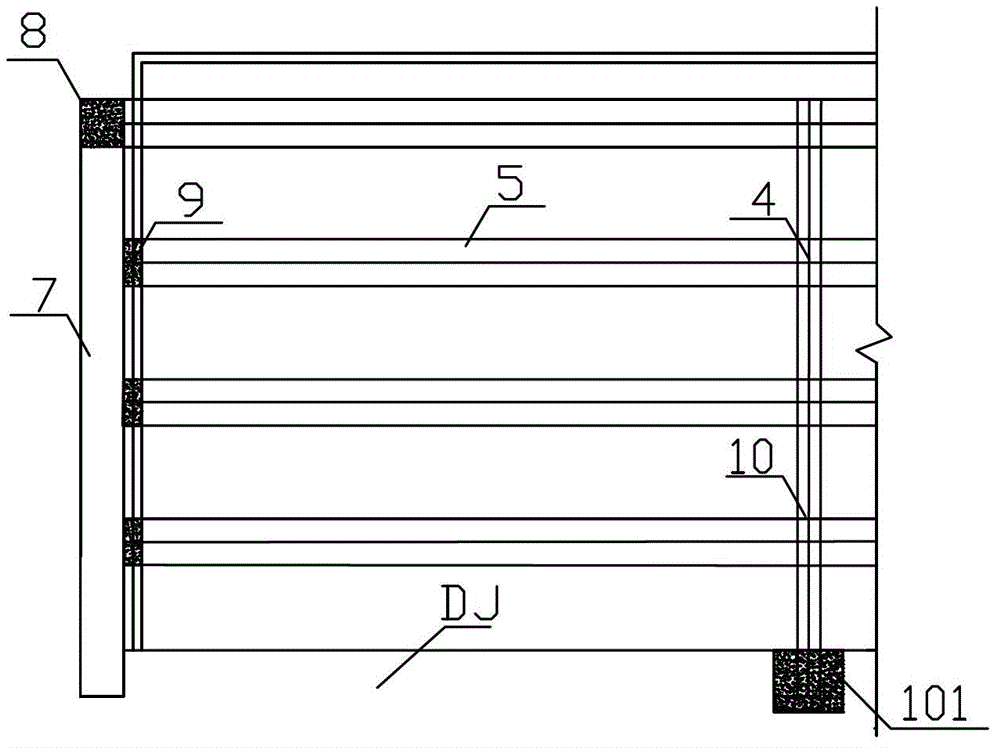
[0067] At first, the construction of the steel structure support column is carried out at the same time as the construction of the wall retaining structure 7 at the side of the foundation pit. The steel structure support column 10 is stretched into the soil by means of drilled piles, and the bottom 101 of the steel structure support column is anchored with concrete pouring (see image 3 , Figure 6 ), when the strength of the anchor concrete at the bottom is sufficient, backfill and compact with earthwork; the retaining wall structure at the edge of the foundation pit can be in the form of an underground diaphragm wall or a supportable row of piles or a steel sheet pile;
[0068] B. Carry out single-layer construction of internally supported three-dimensional support structure ...
PUM
 Abstract
Description
Claims
Application Information