
High-speed friction interface optical in-situ observation precision friction wear testing machine

A friction and wear test, friction interface technology, applied in the direction of testing wear resistance, measuring device, force/torque/work measuring instrument, etc., to achieve the effect of reducing friction interface overturning and stable loading

Active Publication Date: 2021-03-23
HEFEI UNIV OF TECH
View PDF12 Cites 3 Cited by
  • Summary
  • Abstract
  • Description
  • Claims
  • Application Information

AI Technical Summary

Problems solved by technology

However, it is rare to see a friction and wear testing machine capable of in-situ observation of the high-speed friction interface

Method used


Image

  • High-speed friction interface optical in-situ observation precision friction wear testing machine
  • High-speed friction interface optical in-situ observation precision friction wear testing machine
  • High-speed friction interface optical in-situ observation precision friction wear testing machine

Examples


Embodiment Construction

[0067] In order to make the purpose, technical solutions and advantages of the embodiments of the present invention clearer, the technical solutions in the embodiments of the present invention will be clearly and completely described below in conjunction with the embodiments of the present invention. Obviously, the described embodiments are part of the present invention Examples, not all examples. Based on the embodiments of the present invention, all other embodiments obtained by persons of ordinary skill in the art without creative efforts fall within the protection scope of the present invention.

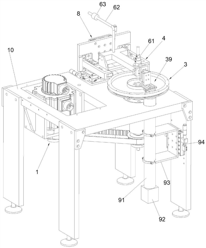
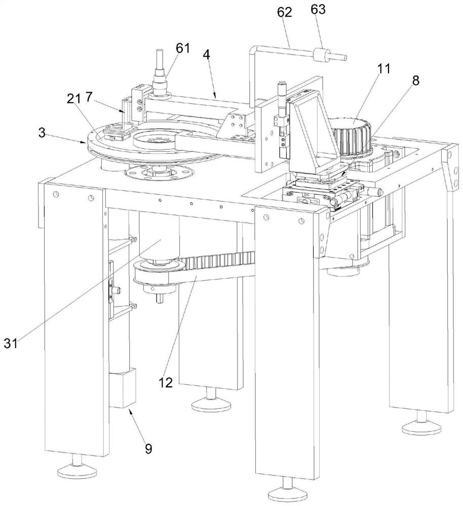
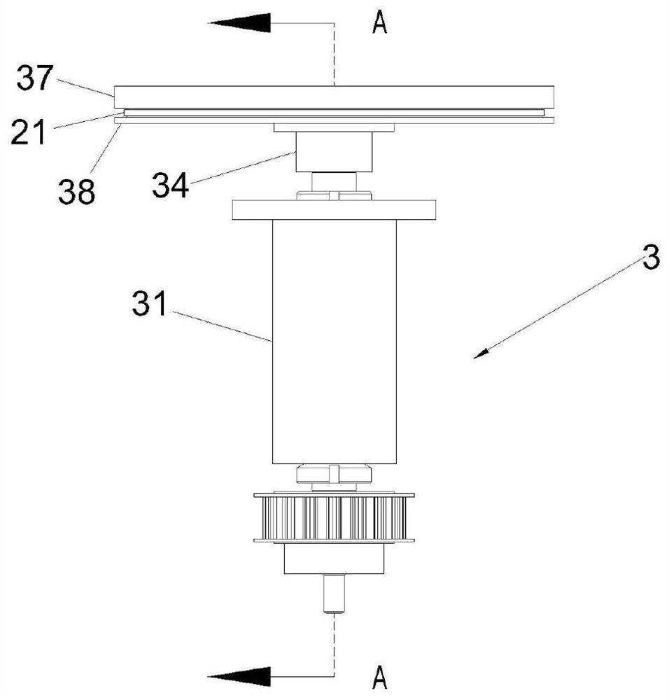
[0068] Please refer to Figure 1 to Figure 24 , the structure of the high-speed friction interface optical in-situ observation precision friction and wear testing machine of this embodiment is as follows:

[0069] The test unit is set, the lower sample 21 in the test unit is horizontally set, supported by the lower support unit and constitutes a synchronous rotary member, powere...


PUM


Abstract

The invention provides a high-speed friction interface optical in-situ observation precision friction wear testing machine, which is characterized in that a lower sample in a testing unit is powered by a driving unit and can rotate around a central axis, an upper sample in the testing unit is suspended above the lower sample through an upper cantilever beam unit, the levelness of the upper sampleand the position of the upper sample relative to the lower sample can be adjusted through a position adjusting unit, the lower end face of the upper sample and the upper end face of the lower sample can be in follow-up contact under the action of a loading force applied by a loading unit and the action of a pair of large-interval cantilever beam plate spring structures of the upper cantilever beamunit to form a pair of friction pairs, the loading force can be finely adjusted through an adjusting screw rod and an adjusting weight, the test unit measures the magnitude of the loading force applied by the loading unit through a loading force sensor, and measures the magnitude of the friction force between the pair of friction pairs through a friction force sensor. According to the invention,stable loading can be realized, the stability of the friction interface is ensured, and the precise adjustment of the loading force and the adjustment of the inclination of the friction interface canbe realized.

Description

technical field [0001] The invention relates to a testing device, more specifically a high-speed friction interface optical in-situ observation precision friction and wear testing machine. Background technique [0002] Tribology mainly studies the phenomena of friction, wear and lubrication on two surfaces with mutual motion. As one of the important methods of tribology research, experimental research requires a high-precision, fully functional testing machine as a support. Tribological performance testing The testing machine can be divided into reciprocating type, pin-on-disk type, end-face contact type, ring block type and four-ball type according to the form of friction pair contact and movement. For some traditional friction and wear tests such as pin-on-disc type As far as the machine is concerned, in the design of its loading structure, the loading method of lever weight is generally used. This method naturally has many shortcomings, mainly because 1) the friction at ...

Claims


Application Information

Patent Timeline
Patent Type & Authority Applications(China)
IPC IPC(8): G01N3/56G01L5/00
CPCG01N3/56G01L5/00Y02T90/00
Inventor 叶家鑫李龙龙孙魏陈祥雨王伟刘焜
Owner HEFEI UNIV OF TECH
Learn More