Sliding disc type axial plunger pump

A technology of axial piston pump and sliding plate type, which is applied in the direction of variable displacement pump components, pumps, pump elements, etc., to achieve the effects of simplified structure, small inertia and reduced lateral force

Pending Publication Date: 2022-05-31
钟彪
View PDF3 Cites 0 Cited by
  • Summary
  • Abstract
  • Description
  • Claims
  • Application Information

AI Technical Summary

Problems solved by technology

[0005] The purpose of the present invention is to provide a novel axial piston pump structure aimed at the problems existing in the current sliding plate axial piston pump, which aims to further reduce the axial force of the bearing, improve the working condition of th

Method used


Image

  • Sliding disc type axial plunger pump
  • Sliding disc type axial plunger pump
  • Sliding disc type axial plunger pump

Examples


Embodiment 1

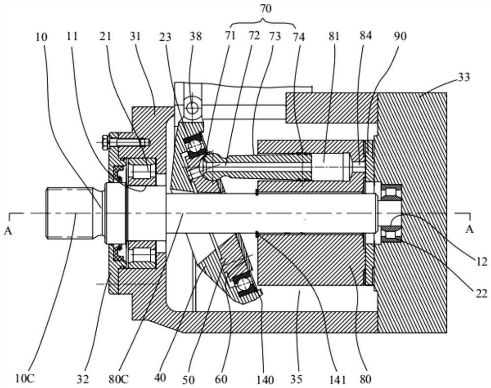
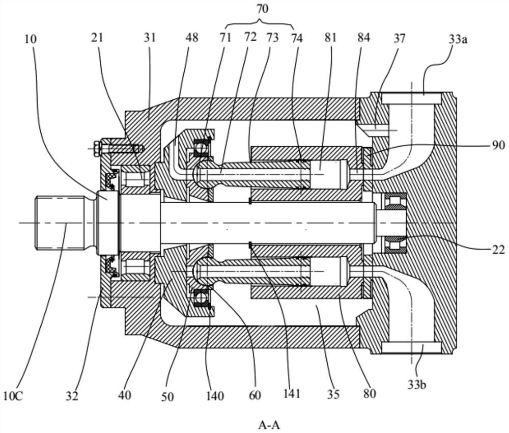
[0053] like Figures 1 to 11 As shown, it is a preferred embodiment of the axial piston pump of the present invention. In the preferred embodiment shown, the piston pump is a through-shaft type piston pump, including a main shaft 10, a housing 31, a first bearing 21. The second bearing 22, the distribution sliding plate pair, the plunger pair, the distribution pair and the rear end cover 33, the rear end cover 33 is provided with a communication groove 37 that communicates with the housing cavity 35, the main shaft of the main shaft 10 The axis 10C coincides with the cylinder axis 80C of the cylinder block 80 . One end of the main shaft 10 penetrates the distribution sliding plate pair and extends out of the housing 31 and is supported on the first bearing 21 , and the other end penetrates the distribution pair and is supported on the second bearing. 22, the cylinder body 80 is supported on the main shaft 10 and is connected with the main shaft through a key to realize synchro...

Embodiment 2

[0080] like Figure 13 As shown, another embodiment of the present invention is shown. The difference from Embodiment 1 is that an impeller 150 is provided on the outer periphery of the cylinder block 80 .

[0081] The impeller 150 is fixed on the cylinder block 80 and rotates synchronously with the cylinder block. Under the action of the impeller, the oil inside the casing forms a certain oil pressure and moves in a directional motion, that is, the oil is driven toward the oil inlet groove 48 of the swash plate 40 . The advantages of this structure are as follows: First, the flow of hot oil in the cavity 35 of the casing is accelerated, so that it leaves the vicinity of the friction pair as soon as possible to reduce the influence of high temperature on the friction pair; second, the oil suction flow on the sliding plate side is increased, and the oil absorption performance is enhanced. .

Embodiment 3

[0083] like Figures 14 to 18 As shown, another embodiment of the present invention is shown, and the difference from Embodiment 1 lies in the difference between the position of the valve plate sliding plate pair and the valve pair, and the difference in the distribution channel caused by the difference , and other structures can be referred to in Example 1.

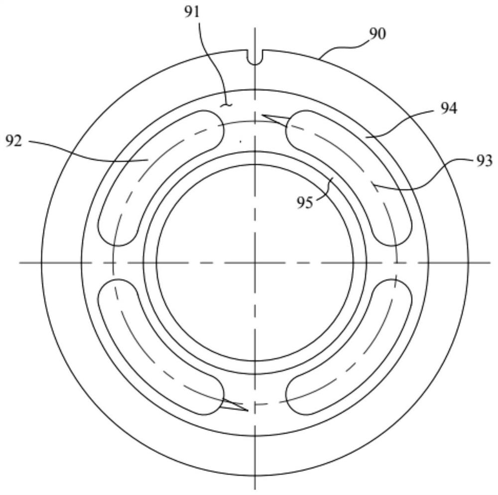
[0084] The distribution pair includes a cylinder block 80 and a distribution plate 90 abutting on the casing 31 . The cylinder block 80 and the distribution plate 90 are supported in a hydrostatic manner and transmit the axial force to the casing. The distribution pair is a single valve. To the low pressure distribution pair, the distribution pair includes the end of the cylinder body and the distribution plate 90 supported on the housing 31 , the end of the cylinder body and the end surface of the distribution plate 90 form a gap-fitted hydrostatic oil film support and the two keep sliding In cooperation, a low pressur...


PUM


Abstract

The sliding disc type axial plunger pump comprises a flow distribution sliding disc pair, a plunger pair and a flow distribution pair, the flow distribution sliding disc pair comprises a swash plate and a sliding disc supported on the swash plate, the sliding disc is of an integral structure, kidney-shaped holes communicated with center holes of plungers are formed in the sliding disc, and the plunger pairs are arranged in the kidney-shaped holes. A low-pressure oil distribution hole serving as an oil inlet channel is formed in the portion, opposite to the low-pressure plunger hole, of the swash plate supporting face, static pressure supporting is formed by the portion, opposite to the high-pressure plunger hole, of the swash plate supporting face and a kidney-shaped hole of the sliding plate, and the low-pressure oil distribution hole is communicated with a shell cavity through an oil inlet groove formed in the swash plate. Low-pressure oil enters a plunger hole of the cylinder body from a low-pressure flow distribution opening and an oil inlet groove or a groove-shaped low-pressure opening of the swash plate in a double-way mode, high-pressure oil is discharged from a high-pressure flow distribution opening of the flow distribution plate or a groove-shaped high-pressure opening of the swash plate in a single-way mode, and suction and discharge of hydraulic oil are achieved. The axial stress of the bearing can be further reduced, the stress working condition of the bearing is improved, the self-suction capacity is improved, the oil temperature is reduced, the working reliability of the plunger pump is improved, and the working life of the plunger pump is prolonged.

Description

technical field [0001] The invention belongs to the technical field of hydraulic transmission and control, and particularly relates to a sliding plate type axial piston pump. Background technique [0002] The axial piston pump is one of the most widely used hydraulic components in modern hydraulic transmission. Among them, the hingeless inclined shaft pump and the sliding shoe swash plate axial piston pump are the most widely used and the most important two types of shafts. to the plunger pump. The inclined shaft pump and the sliding shoe swash plate type have their own characteristics. At present, these two kinds of pumps are still in competition, and they are both constantly improving and developing. [0003] The swash plate type plunger pump is widely used due to its simple and compact structure, small volume and light weight. It realizes stepless variable through the swash plate swing, the inertia of the variable is small, and the variable response speed is relatively f...

Claims


Application Information

Patent Timeline
IPC IPC(8): F04B1/22F04B1/2042F04B1/2078F04B1/2085F04B1/2064F04B1/2035F04B1/2014F04B1/122F04B53/08
CPCF04B1/22F04B1/2042F04B1/2078F04B1/2085F04B1/2064F04B1/2035F04B1/2014F04B1/122F04B53/08
Inventor 钟彪
Owner 钟彪
Why Eureka
Try Eureka