
Flip folding device for mobile early warning radar antenna array

A technology of early warning radar and antenna array, applied in the direction of antenna array, rotating antenna, antenna, etc., can solve the problems of easy dislocation of mechanism, hydraulic cylinder stroke error, stuck antenna array, etc., achieve stable flipping and folding, and increase reduction ratio , the effect of strong reliability

Active Publication Date: 2019-12-31
JINGZHOU NANHU MACHINERY CO LTD
View PDF8 Cites 3 Cited by
  • Summary
  • Abstract
  • Description
  • Claims
  • Application Information

AI Technical Summary

Problems solved by technology

[0003] The erection and retraction of the existing antenna array generally adopts a hydraulic cylinder to promote a four-link folding and flipping mechanism; this mechanism has the following defects: 1. When the radar antenna array is wide and the wind load is large, the mechanism is easy to Misalignment leads to deformation of the array, causing the antenna array to be stuck to each other, making it difficult to realize the folding function; 2. The mechanism does not have a self-locking function, and an auxiliary positioning and locking device must be installed after the antenna array is turned over; 3. Due to the hydraulic cylinder There is a stroke error, which makes it difficult to ensure the operation accuracy of the four-bar linkage mechanism, which leads to the inability of the antenna array to fully shrink in place; 4. The hydraulic cylinder and the four-bar linkage mechanism are large in size, and the iron and air transportation will exceed the limit; therefore, it is very necessary to improve them

Method used


Image

  • Flip folding device for mobile early warning radar antenna array
  • Flip folding device for mobile early warning radar antenna array
  • Flip folding device for mobile early warning radar antenna array

Examples


Embodiment Construction

[0023] Below in conjunction with the accompanying drawings, the embodiment of the turning and folding device for the mobile early warning radar antenna array will be described in further detail (see Figure 1-7 ):

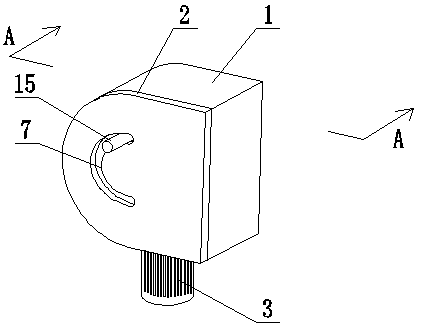
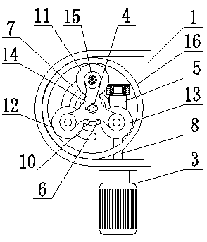
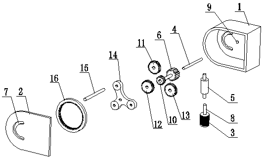
[0024] The turning and folding device for the mobile early warning radar antenna array is composed of a housing 1, a cover plate 2, a transmission motor 3, an output shaft 4, a worm 5, a worm wheel 6 and a planetary gear mechanism; the housing 1 is shaped like a rectangular box The cover plate 2 is fixedly installed on the shell 1 by bolts, a cavity is formed between the shell 1 and the cover plate 2, and the cover plate 2 and the shell 1 are correspondingly opened with a limit groove 7, and the limit groove The shape of 7 is arc shape.

[0025] The transmission motor 3 is installed on the casing 1 through the motor support seat, the transmission shaft 8 of the transmission motor 3 extends into the casing 1, and the output shaft 4 is installed between the casing 1...


PUM


Abstract

The invention relates to a flip folding device, in particular to a flip folding device for a mobile early warning radar antenna array. The flip folding device is composed of a shell, a cover plate, aplanetary gear mechanism, etc. A limiting groove is correspondingly formed on the shell and the cover plate. A transmission shaft of the transmission motor fixed on the shell extends into the shell. Aworm rod is arranged on the upper part of the transmission shaft, and a worm wheel is arranged on the output shaft fixed on the side. The worm wheel rotates around the output shaft through meshing transmission with the worm rod. The output shaft is connected with the worm wheel as a whole through the sun gear external gear installed by the bearing. The worm wheel drives the sun gear external gearto rotate around the output shaft. The sun gear inner ring gear of the planetary gear mechanism installed on the output shaft is installed on the inner wall of the shell corresponding to the sun gearouter gear, and the planetary gear A, the planetary gear B and the planetary gear C of the planetary gear mechanism are meshed and connected with the sun gear outer gear and the sun gear inner ring gear. The planet carrier is equipped with a limiting rod corresponding to the position of the planetary gear A. The fast folding and self-locking performance is high, the volume is small, the structureis stable and the reliability is good.

Description

technical field [0001] The invention relates to an overturning and folding device, in particular to an overturning and folding device for a mobile early warning radar antenna array. Background technique [0002] The mobile early warning radar is mainly responsible for the mobile combat tasks of air combat guidance and air alert, and has high mobility, strong anti-jamming and survivability. In order to obtain a longer detection distance, modern early warning radars have increased the power of the radar and enlarged the antenna front, but at the same time it has also affected the high mobility of the ground radar. In order to improve the high mobility of ground radar and meet the requirements of sea, land, and air loading and transportation specifications, the antenna array must be segmented and foldable, that is, the radar antenna array must have the function of automatic folding and flipping. [0003] The erection and retraction of the existing antenna array generally adopt...

Claims


Application Information

Patent Timeline
IPC IPC(8): H01Q1/08H01Q21/00G01S7/02G01S13/02
CPCG01S7/02G01S13/02G01S2013/0245H01Q1/08H01Q1/084H01Q21/00
Inventor 刘世永楚波李文杰
Owner JINGZHOU NANHU MACHINERY CO LTD
Learn More