Vehicle underbody structure

A vehicle, body technology, applied in the field of lower body structure

Active Publication Date: 2020-01-03
TOYOTA JIDOSHA KK
View PDF11 Cites 0 Cited by
  • Summary
  • Abstract
  • Description
  • Claims
  • Application Information

AI Technical Summary

Problems solved by technology

In addition, the symbols in parentheses mentioned above are the symbols used in the following Patent Document 1, and are not related to the symbols used in the description of the embodiments of the present application.

Method used


Image

  • Vehicle underbody structure
  • Vehicle underbody structure
  • Vehicle underbody structure

Examples


Embodiment Construction

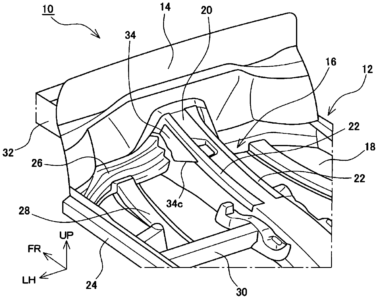
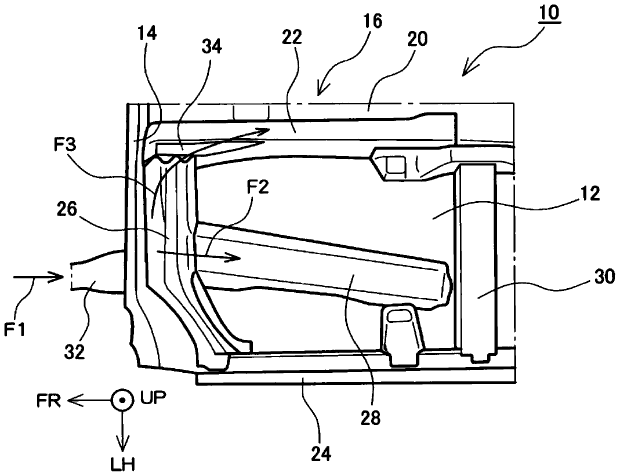
[0023] Embodiments of the present disclosure will be described below with reference to the drawings. figure 1 and figure 2 is a diagram showing an underbody structure 10 of a vehicle, figure 1 It is a perspective view showing a part of the front part of the vehicle compartment, figure 2 It is a plan view showing the part on the front left side of the vehicle compartment. In the following description, unless otherwise specified, words and phrases indicating directions and orientations such as front, front, rear, rear, left, right, side, up, above, down, and below all refer to directions related to vehicles. and orientation. In each drawing, the direction of the arrow FR is forward, the direction of the arrow UP is upward, and the direction of the arrow LH is left. In addition, the direction extending in the front-rear direction of the vehicle is referred to as a longitudinal direction, and the direction extending in the left-right direction of the vehicle is referred to a...


PUM


Abstract

The present disclosure relates to a vehicle underbody structure. On a side face of a floor tunnel (16), a side reinforcement (34) is disposed between a region at which a carriage front wall cross member (26) is connected to the floor tunnel and an upper edge of the side face. An upper reinforcement (22) extends in a longitudinal direction at an upper portion of the floor tunnel (16). The side reinforcement (34) extends rearward with its rear edge (34c) inclining upward. A collision load (F1) input from a side member (32) enters the side face of the floor tunnel (16) via the carriage front wall cross member (26). The collision load (F3), which is transmitted on the floor tunnel (16), is transmitted to the upper reinforcement (22) along the rear edge (34c) of the side reinforcement.

Description

[0001] Cross References to Related Applications [0002] This application claims priority from Japanese Patent Application No. 2018-121797 filed on June 27, 2018, which is hereby incorporated by reference in its entirety, including specification, claims, drawings and abstract . technical field [0003] The present disclosure relates to an underbody structure of a vehicle, and more particularly, to a structure for securing strength at the time of a collision. Background technique [0004] In the following patent document 1, the structure which reinforces the floor tunnel extending front and back at the center of the floor of a vehicle is shown. A collision load input to the front portion (35A) of the floor tunnel is transmitted to the tunnel lower reinforcement (32) via the tunnel upper reinforcement (40). In addition, input from the front side member (68) will be input to the tunnel lower reinforcement (32) via the inner torque box (88). In addition, the above-mentioned c...

Claims


Application Information

Patent Timeline
IPC IPC(8): B62D25/20
CPCB62D25/20B62D25/2018B62D21/15B62D21/155B62D21/157B62D25/2045
Inventor 大场进也太田晃生
Owner TOYOTA JIDOSHA KK
Why Eureka
Try Eureka