Eureka AIR delivers breakthrough ideas for toughest innovation challenges, trusted by R&D personnel around the world.

AR scene design system

A design system and scene technology, applied in the field of AR scene design system, can solve the problems of loss of orientation cognition and visual cognition, reducing the experience of augmented reality technology, and increasing the size of the display screen, so as to increase the experience and occupy a small area. , the effect of convenient operation

Active Publication Date: 2020-01-10
HUNAN UNIV OF ARTS & SCI
View PDF4 Cites 0 Cited by
  • Summary
  • Abstract
  • Description
  • Claims
  • Application Information

AI Technical Summary

Problems solved by technology

However, the traditional augmented reality technology is mostly limited to the user passively wearing the head-mounted display, or even completing the passive operation statically. In the virtual content, although the user can realize multi-directional movement commands, but in the display environment, his body is still, and he does not even need to take steps. The basic settings are made on the premise of maintaining their own safety. If the user realizes his own movement during the use of the helmet display, he will lose direction recognition and visual recognition in the display environment. The degree of danger can be imagined. However, passive movement will greatly reduce the user's experience. This defect greatly reduces the experience of augmented reality technology and becomes a technical barrier to augmented reality technology.
At the same time, in the traditional AR experience, once the video position capture and the head-mounted display are missing, the overall sensory operation will lose its effect. In the state of actively losing the head-mounted display, if you need to move with the content of the enhanced display, it will inevitably take up more space. This increases the overall footprint of the device, and increases the size of the display screen, resulting in an increase in cost

Method used


Image

  • AR scene design system
  • AR scene design system
  • AR scene design system

Examples


Embodiment Construction

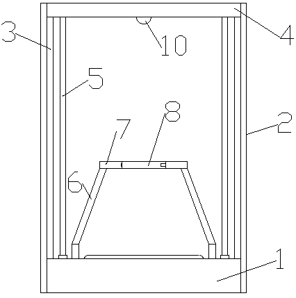
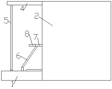
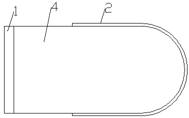
[0025] Such as figure 1 , 2 , 3, 4, 5, 6, 7, 8, and 9, an AR scene design system includes a bottom support box 1, a scene protection plate 2, a top scene protection plate 4 and a scene display 3, the scene The protection plate 2 is fixedly installed on the outside of the bottom support box 1, the top scene protection plate 4 is installed on the inside of the scene protection plate 2 on the top of the bottom support box 1, and the scene display 3 is installed on the top scene protection plate 4 and the bottom support box 1, inside the scene protection plate 2, on the top surface of the bottom support box 1, there is a scene movement simulator installation port 9, and four limit supports are fixedly installed at the four corners of the scene movement simulator installation port 9 Column 6, the tops of four limit support columns 6 are connected with the bottom of the mobile simulation limit ring 7, and the scene movement simulation device is installed in the scene movement simul...


PUM


Abstract

The invention relates to an AR scene design system. Four limiting support columns are fixedly mounted at four corners of a scene movement simulator mounting port; the tops of the four limiting supportcolumns are connected with the bottom of the mobile simulation limiting ring; a scene movement simulation device is mounted in the scene movement simulator mounting opening below the movement simulation limiting ring; a controller is mounted in the bottom supporting box body on one side of the scene movement simulation device; a displacement catcher is fixedly mounted at the bottom of the top scene protection plate above the moving simulation limiting ring; the displacement capturer, the scene displayer and the scene movement simulation device are connected with the controller through wires,the controller is connected with an external computer through an external input and output line, and a user can obtain more real experience compared with traditional augmented display equipment.

Description

technical field [0001] The invention relates to an AR scene design system. Background technique [0002] Augmented reality technology is a technology that ingeniously integrates virtual information with the real world. It widely uses various technical means such as multimedia, 3D modeling, real-time tracking and registration, intelligent interaction, and sensing to combine computer-generated text, images, 3D models, music, video and other virtual information are simulated and applied to the real world. The two kinds of information complement each other, thereby enhancing the real world. Augmented reality is referred to as AR for short, and augmented reality technology is also called augmented reality. AR augmented reality technology is a relatively new technical content that promotes the integration of real world information and virtual world information content. The physical information that is relatively difficult to experience in the scope is simulated and processed on t...

Claims


Application Information

Patent Timeline
Patent Type & Authority Applications(China)
IPC IPC(8): G06T19/00F16M11/04F16M11/20
CPCG06T19/006F16M11/04F16M11/20
Inventor 蒋蕾邱陵陈潇潇程谊万瑶
Owner HUNAN UNIV OF ARTS & SCI
Why Eureka
Eureka Blog
Learn More