
Light source control circuit

A light source control and circuit technology, applied in the field of lighting, can solve problems such as the inability of the light source to illuminate, the battery is insufficient to light the light source, and the inability to supply power to the light source, and achieves the effect of avoiding poor safety.

Pending Publication Date: 2020-01-17
WAROM TECH INC
View PDF0 Cites 0 Cited by
  • Summary
  • Abstract
  • Description
  • Claims
  • Application Information

AI Technical Summary

Problems solved by technology

[0002] At present, there are light sources for lighting in many fields. In the case of power failure, that is, the mains power cannot supply power to the light source, some places need to provide an emergency power supply circuit for the light source to prevent the light source from being unable to illuminate when the power is off.
[0003] At present, it is possible to control whether the backup battery supplies power to the light source through a switch. When the power is cut off, turn on the switch to enable the backup battery to supply power to the light source. The on-off switch between the batteries is set on the strong power line connecting the battery to the light source. When switching the emergency state, it is necessary to cut off the strong power, which is extremely dangerous, and when the switch is turned off, there is no additional power source to charge the battery. , resulting in the possibility of insufficient battery power in emergency situations, for example, the remaining power of the battery is not enough to turn on the light source

Method used


Image

  • Light source control circuit
  • Light source control circuit
  • Light source control circuit

Examples


Embodiment Construction

[0035] The present invention will be further described in detail below in conjunction with the accompanying drawings and embodiments. It should be understood that the specific embodiments described here are only used to explain the present invention, but not to limit the present invention. In addition, it should be noted that, for the convenience of description, only some structures related to the present invention are shown in the drawings but not all structures.

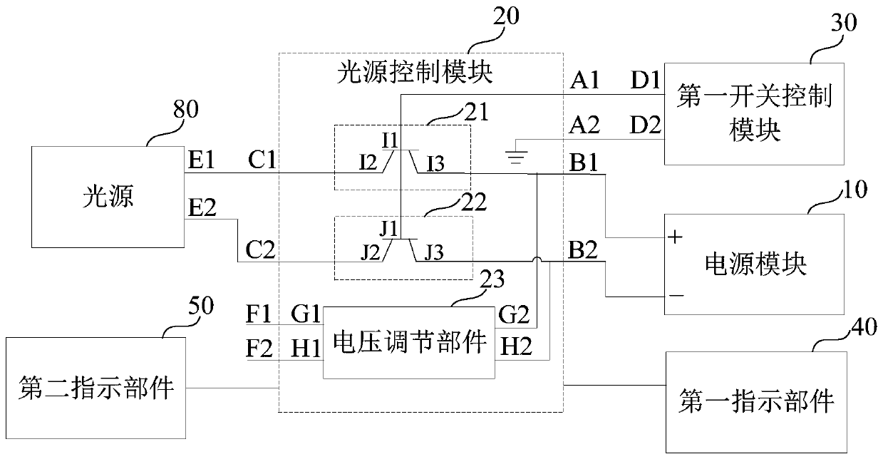
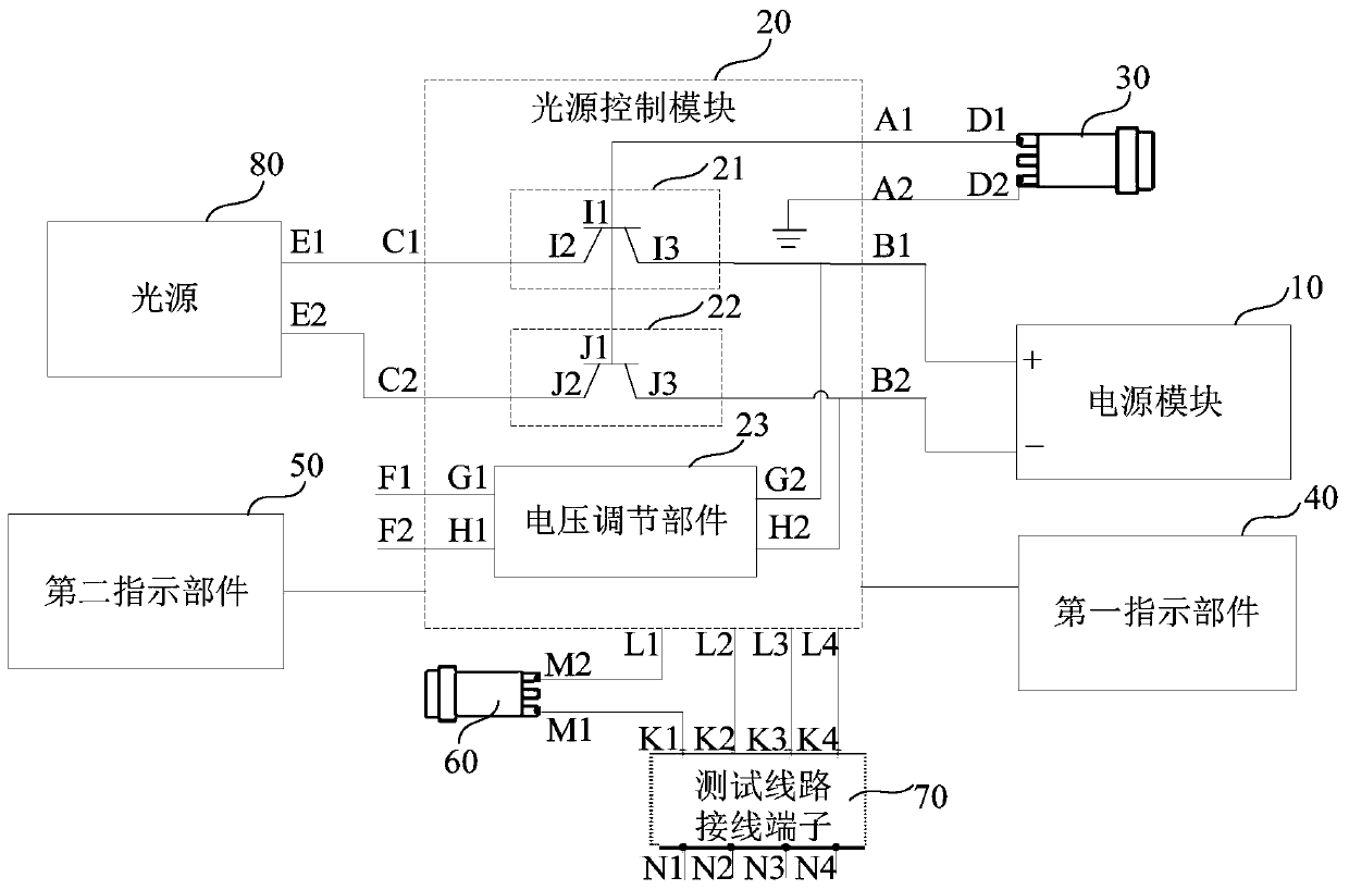
[0036] figure 1 It is a schematic structural diagram of a light source control circuit provided by an embodiment of the present invention, refer to figure 1 , the light source control circuit includes: a power supply module 10, a light source control module 20 and a first switch control module 30, the light source control module 20 is electrically connected to the power supply module 10 and the first switch control module 30, and the light source control module 20 The electricity is charged to the power supply mo...


PUM


Abstract

The embodiment of the invention discloses a light source control circuit, which comprises a power supply module, a light source control module and a first switch control module, and is characterized in that the light source control module is electrically connected with the power supply module and the first switch control module, the light source control module charges the power supply module according to the connected mains supply, and the first switch control module controls the connection state of a path connecting the power supply module and a light source in the light source control moduleaccording to the own switch state of the first switch control module. Through the technical scheme of the invention, the problem of insufficient electric quantity of the power supply module under anemergency condition is avoided, the first switch control module can control a weak current circuit in the light source control module, and the problem of worse safety caused by directly cutting off astrong current is avoided.

Description

technical field [0001] The embodiments of the present invention relate to the technical field of lighting, and in particular to a light source control circuit. Background technique [0002] At present, there are light sources for lighting in many fields. In the event of a power outage, that is, the mains power cannot supply power to the light source, some places need to provide an emergency power supply circuit for the light source to prevent the light source from being unable to illuminate when the power is off. [0003] At present, it is possible to control whether the backup battery supplies power to the light source through a switch. When the power is off, turn on the switch to enable the backup battery to supply power to the light source. The on-off switch between the batteries is set on the strong power line connecting the battery to the light source. When switching the emergency state, it is necessary to cut off the strong power, which is extremely dangerous, and when...

Claims


Application Information

Patent Timeline
Patent Type & Authority Applications(China)
IPC IPC(8): H05B47/10
Inventor 王亚德章明高卿月梅周青
Owner WAROM TECH INC
Learn More