A kind of distribution cabinet line installation structure and using method thereof

A technology for installation structures and power distribution cabinets, which is applied in the directions of busbar/line layout, electrical components, equipment for connecting/terminating cables, etc. Wire damage and other problems, to achieve the effect of clear arrangement, tight fit, and avoid falling off

Active Publication Date: 2021-03-26
ANHUI MINGKUN ELECTRICAL APPLIANCE EQUIP
View PDF9 Cites 0 Cited by
  • Summary
  • Abstract
  • Description
  • Claims
  • Application Information

AI Technical Summary

Problems solved by technology

[0004] The main purpose of the present invention is to provide a circuit installation structure of a power distribution cabinet and its use method, which mainly solves the following technical problems: when the wires from the outside enter the inside of the power distribution cabinet, the arrangement of the wires is messy, and the wires at the interface It is easy to damage the wires. When a fire occurs inside the power distribution cabinet, the fire is easy to spread to the outside of the power distribution cabinet; secondly, the wires entering the power distribution cabinet are entangled with many wires due to the narrow space. It is convenient to carry out the wiring operation. Therefore, we propose a power distribution cabinet line installation structure and its use method

Method used


Image

  • A kind of distribution cabinet line installation structure and using method thereof
  • A kind of distribution cabinet line installation structure and using method thereof
  • A kind of distribution cabinet line installation structure and using method thereof

Examples


Embodiment 1

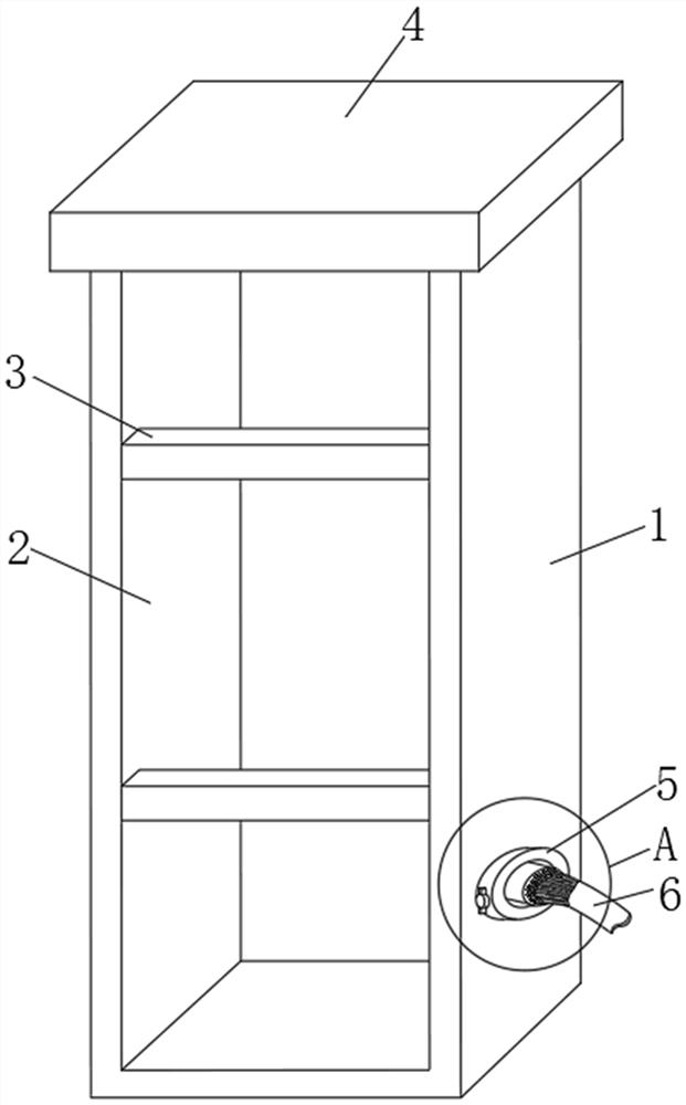
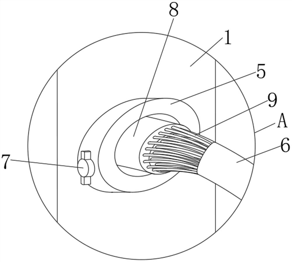
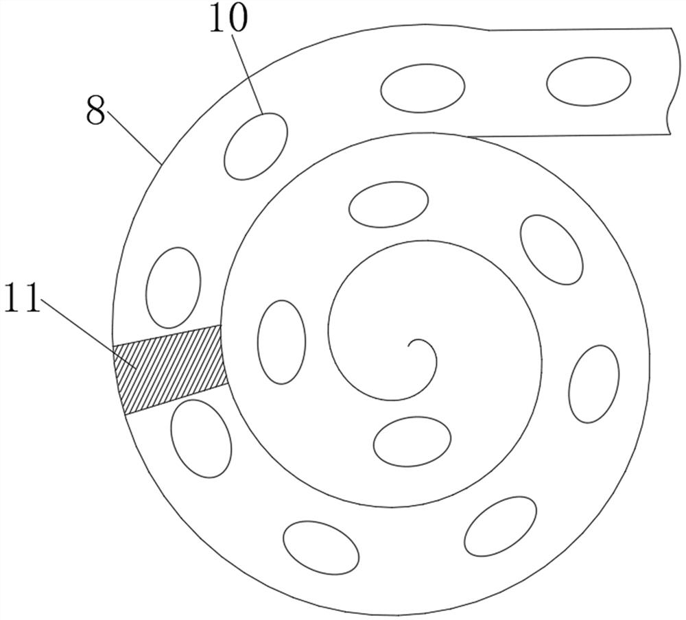
[0032] Such as Figure 1-5As shown, a circuit installation structure of a power distribution cabinet includes a No. 1 side plate 1 and a No. 2 side plate 2. The upper ends of the No. 1 side plate 1 and the No. Two sets of cross braces 3 are fixedly installed on the front end of the No. 2 side plate 2. A connecting hole 28 is opened on the No. 1 side plate 1. A fixing ring 5 is fixedly installed on one side of the connecting hole 28. The inside of the fixing ring 5 is provided with a rubber Pad 8, the inside of the rubber pad 8 is provided with fixing holes 10, the rubber pad 8 includes a cover layer 16 and a support layer, the lower end of the cover layer 16 is provided with several groups of first grooves 12, and the lower ends of the first grooves 12 are arranged on both sides. A connection block 15 is fixedly installed, and several groups of second grooves 13 are provided on the upper end of the support layer, and connection grooves 14 are arranged on both sides of the seco...

Embodiment 2

[0041] The present invention provides a method for using a circuit installation structure of a power distribution cabinet, and the specific steps are as follows:

[0042] Step 1: Place the wires in the casing 6 on the second groove 13 respectively, place the covering layer 16 on the support layer, make the connecting block 15 coincide with the connecting groove 14, and then place the rubber pad 8 according to the Figure 4 Winding in the direction of the arrow in the middle, winding into image 3 shape;

[0043] Step 2: Insert the wrapped rubber pad 8 into the connecting hole 28 and the fixed ring 5, rotate the two sets of No. 1 rotating blocks 7, so that the No. 1 screw 23 rotates in the No. 1 threaded hole, and the rotating column 24 is in the rotating groove 26. internal rotation, so that the fastening block 25 squeezes and fixes the rubber pad 8, so that the arrangement of the many wires leading into the distribution cabinet is more orderly;

[0044] Step 3: Thread the wi...


PUM


Abstract

The invention discloses a power distribution cabinet circuit installation structure, which includes a first side plate and a second side plate. An upper top plate is fixedly installed on the upper ends of the first side plate and the second side plate. Two groups of cross braces are fixedly installed on front ends of the first side plate and the second side plate. The power distribution cabinet circuit installation structure and a use method thereof can wrap a large number of wires together through a power distribution cabinet, integrate circuits installed in the power distribution cabinet, avoid tangled wires, wraps the wires tightly by using rubber pads, and can fix the rubber pads and the power distribution cabinets firmly. A flame-retardant insulating rubber layer can effectively isolate and protect a circuit on fire when the interior of the power distribution cabinet malfunctions and catches a fire. The circuit installation structure can enter the respective channels for wiring according to the different functions of the wires so as to make the wiring arrangement clear, and can fix the wires entering the power distribution cabinet to provide better use prospects.

Description

technical field [0001] The invention relates to the field of circuit installation of a power distribution cabinet, in particular to a circuit installation structure of a power distribution cabinet and a use method thereof. Background technique [0002] Power distribution cabinets are divided into power distribution cabinets, lighting distribution cabinets, and metering cabinets. They are the final equipment of the power distribution system. Power distribution cabinets are collectively referred to as motor control centers. , The motor control center is used in occasions where the load is concentrated and there are many circuits. The connection of the wires of the power distribution cabinet occupies a large proportion in the work of an electrician. A distribution cabinet line installation structure is required. [0003] The existing wiring installation structure of the power distribution cabinet has certain disadvantages in use. When the external wires enter the interior of t...

Claims


Application Information

Patent Timeline
Patent Type & Authority Patents(China)
IPC IPC(8): H02B1/20H02G3/04H02G1/14
CPCH02B1/20H02G1/14H02G3/045
Inventor 刘长胜
Owner ANHUI MINGKUN ELECTRICAL APPLIANCE EQUIP
Why Eureka
Try Eureka