Optical device for painters

An optical device, a painter's technique, applied in optics, optical components, decorative arts, etc., can solve the problems of non-existence, bulky and bulky devices, etc.

Inactive Publication Date: 2020-01-21
J 加西亚 阿梅诺斯
View PDF5 Cites 0 Cited by
  • Summary
  • Abstract
  • Description
  • Claims
  • Application Information

AI Technical Summary

Problems solved by technology

However, for example for drawing pictures, these devices are often bulky and bulky, require a power source and are only capable of drawing printed pictures and not moving images
[0007] Therefore, as a reference to the prior art, it must be noted that although many different devices are known on the market to the extent described herein, at least to the applicant's knowledge, there is no such device that has the same characteristics as the painter's optics claimed herein. Devices with the same or similar technical and structural features as the specific features of the device

Method used


Image

  • Optical device for painters
  • Optical device for painters
  • Optical device for painters

Examples


Embodiment Construction

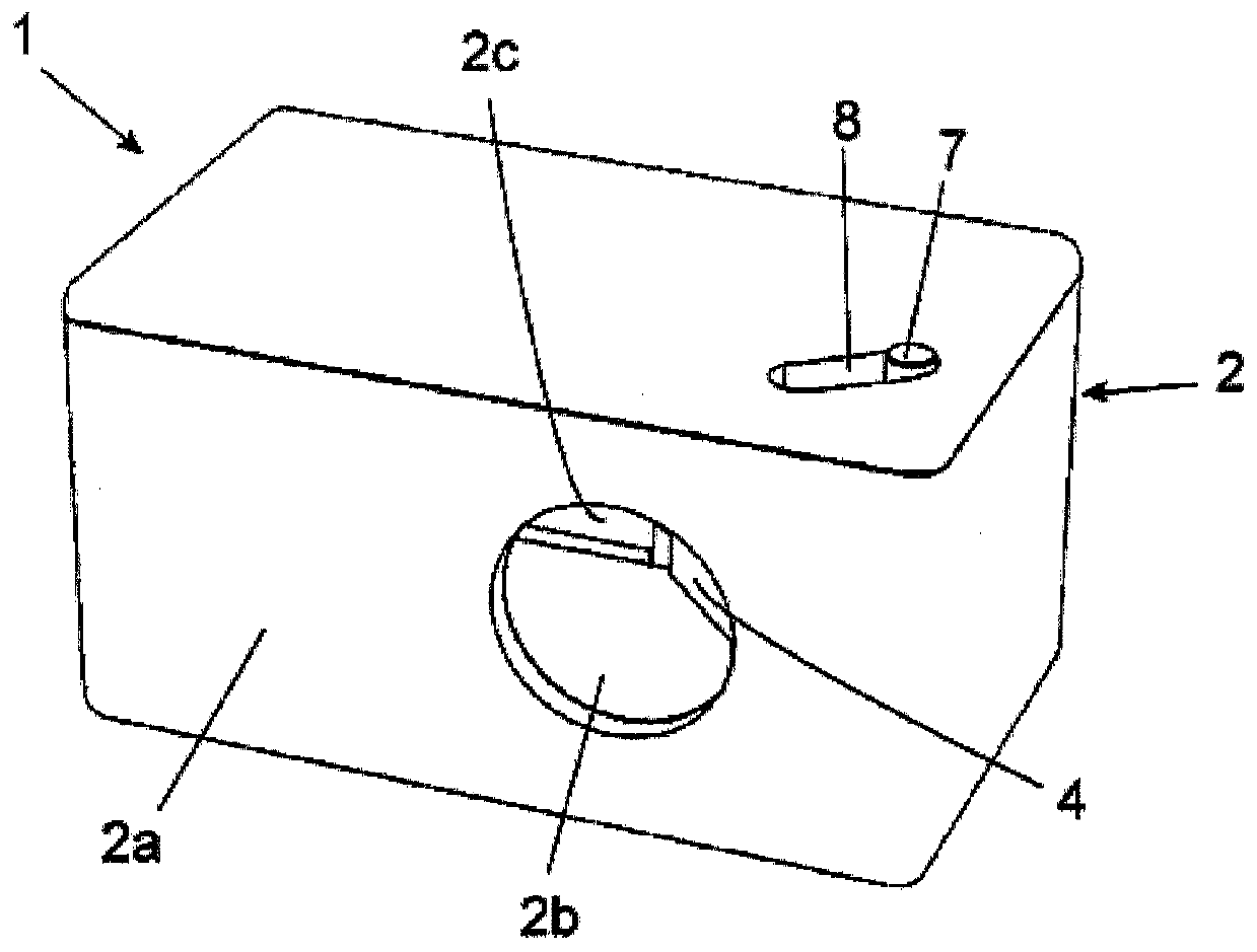
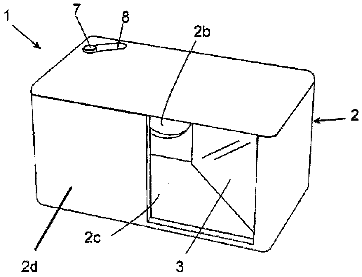
[0018] Based on the above figures, and according to the figures, there is shown a non-limiting example of a painter's optical device of the present invention, comprising the parts and elements shown and described in detail below.

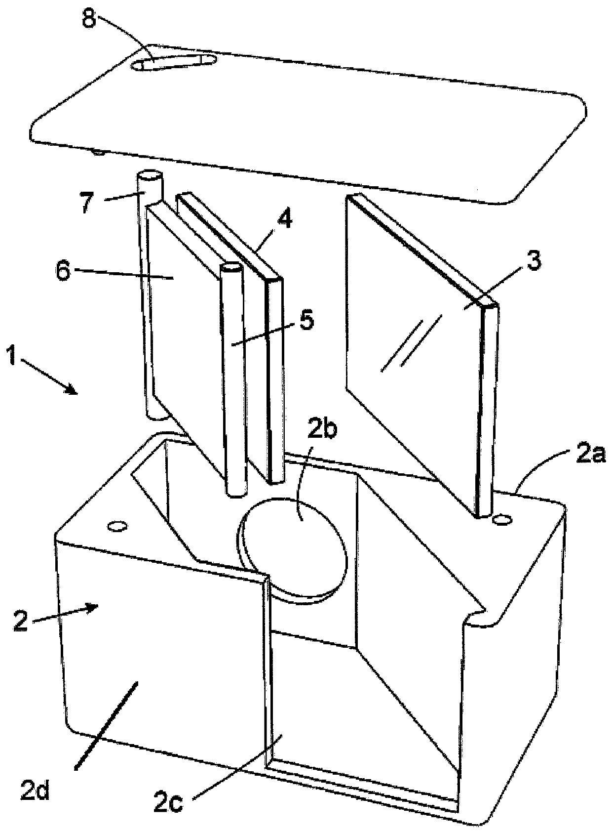
[0019] Thus, as shown in said figures, the device 1 of the invention basically comprises a support structure 2 with at least two mirrors 3, 4 arranged opposite each other, the two mirrors 3, 4 are placed so that they are at an angle of approximately 45° to the rear side 2a of the support structure 2, in this way the image of the scene to be shown e captured by the first mirror 3 at the front side of the device 1 Reflected into a second mirror 4 facing the first mirror 3, the image reflected onto the second mirror 4 is received by an observer o at the rear side of the device.

[0020] One of the mirrors, for example the second mirror 4, is oscillating so that the second mirror 4 can change its position angle a relative to the rear side 2a of the supp...


PUM


Abstract

The invention relates to an optical device for painters, which can be used to make life drawings, said device being positioned facing the observer, between the scene, image or model to be copied and the working surface. The device comprises a supporting structure (2) including at least two mirrors (3, 4) disposed facing one another, both positioned to form an angle, of approximately 45 degrees, relative to the rear surface of the structure, such that the image, located on the front side of the device (1), received by a first mirror (3) is reflected onto a second mirror (4) and the image reflected in the second mirror is received by the observer located on the rear side of the device (1). One of the mirrors can pivot such as to vary the angle (a) at which it is positioned relative to the rear face (2a) of the structure (2) and, consequently, relative to the first mirror (3), in order to control the orientation of the reflected image received and to adjust same as appropriate. The secondmirror (4) can tilt and is secured to the structure (2) by means of a coupling that can move on a shaft (5) solidly connected to a plate (6) against which said mirror (4) is placed, which plate can pivot and be moved manually about the shaft (5) by means of the movement of a spring (7) that can travel along a curved groove (8) provided in the structure (2). The structure takes the form of a caseenclosed by walls on each of the sides thereof and equipped with openings (2c, 2b) through which the image to be reproduced is received and reflected. The openings in the case formed by the structure(2) consist of a rectangular opening (2c) provided in the front face (2d) and a circular opening (2b) provided in the rear face (2a) and oriented towards the observer (o).

Description

[0001] purpose of invention [0002] As shown in this specification, the present invention relates to a painter's optical device, which provides advantages and novel features in order to achieve the above objects, which will be described in detail below. [0003] The object of the present invention is a device intended to be used as a painter or designer's tool in order to copy biological models, for this purpose the device is based on a box with a number of strategically placed mirrors Yes, when these mirrors are placed correspondingly in front of the field of view between the scene or image to be traced and the work surface, the device provides the optical effect of superposition of the two images. [0004] Application field [0005] The present invention finds application in the field of optical equipment, optical devices and optics industry, more particularly in the field of support tools for freehand drawing and design works. Background technique [0006] In the fields ...

Claims


Application Information

Patent Timeline
Patent Type & Authority Applications(China)
IPC IPC(8): B44D3/00
CPCB43L13/10B44D3/22G02B17/026G09B11/10B44D3/00G02B17/00
Inventor J·加西亚·阿梅诺斯
Owner J 加西亚 阿梅诺斯
Why Eureka
Try Eureka