Supercharge Your Innovation With Domain-Expert AI Agents!

Safety valves for hydraulic systems

A technology of hydraulic system and safety valve, applied in the field of safety valve

Active Publication Date: 2022-03-04
萨尔瓦托雷布福
View PDF15 Cites 0 Cited by
  • Summary
  • Abstract
  • Description
  • Claims
  • Application Information

AI Technical Summary

Problems solved by technology

Again, these fluids are much more expensive than mineral oil

Method used


Image

  • Safety valves for hydraulic systems
  • Safety valves for hydraulic systems
  • Safety valves for hydraulic systems

Examples


Embodiment Construction

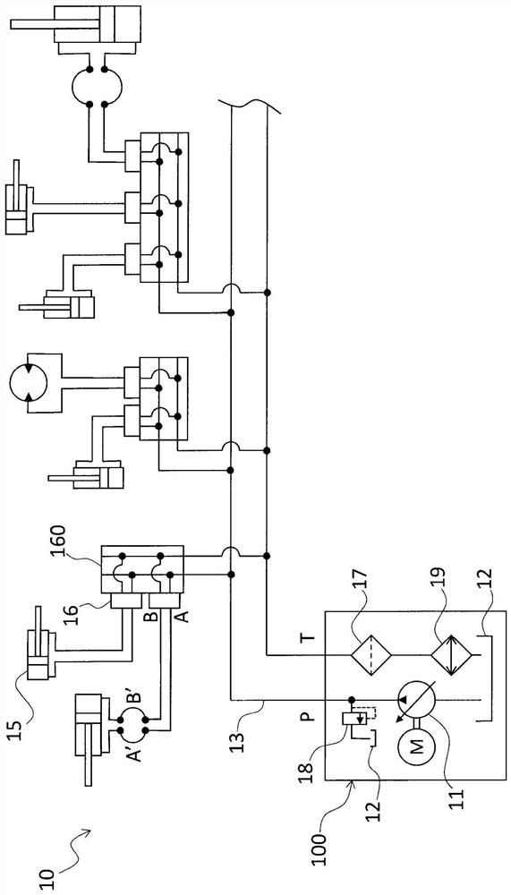
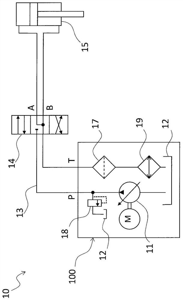
[0035] The invention relates to a safety valve 20 for a hydraulic system 10 . The safety valve 20 includes: an inlet 21 , an outlet 22 and a channel 23 .

[0036] The safety valve 20 has a predetermined maximum flow rate of oil Q m . The channel 23 is adapted to ensure the flow of operating oil from the inlet 21 to the outlet 22, the flow of the operating oil having a value Q between zero and the maximum operating flow rate m the velocity between them.

[0037] Furthermore, the safety valve 20 according to the invention comprises emergency blocking means 24 positioned along the channel 23 . The emergency blocking device 24 is adapted to pass the flow rate Q exceeding the maximum operating flow along the channel 23 m The flow of oil is actuated and adapted to close the passage 23.

[0038] Preferably, the emergency blocking means 24 are adapted to close the channel 23 so that the flow rate of oil reaching the outlet 22 is equal to zero.

[0039] The safety valve 20 accord...


PUM


Abstract

The invention relates to a safety valve (20) for a hydraulic system. The valve comprises: an inlet (21), an outlet (22), and a channel (23). The valve has a predetermined maximum operating flow rate of oil Q m . The channel guarantees the oil operating flow flowing from the inlet to the outlet, the oil operating flow has a value Q between zero and the maximum operating flow rate m the velocity between them. The valve according to the invention also comprises emergency blocking means (24) positioned along the channel. emergency blocking device by exceeding the maximum operating flow rate Q along the channel m The oil flow rate is actuated and is suitable for closing the channel. The invention also relates to a safety valve assembly and a hydraulic system comprising the safety valve.

Description

technical field [0001] The invention relates to a safety valve for a hydraulic system. A typical but not exclusive application of the invention is the steel industry. Background technique [0002] Hydraulic systems are used extensively in the manufacturing, industrial and mobility fields for power transmission. In fact, these systems allow significant power to be handled with components that are of much smaller size and weight than other types of systems using different technologies. [0003] In hydraulic power transmission, a large volume of incompressible oil is used to transmit pressure from a pump system to an actuator through a suitable circuit. Typically, a hydraulic system includes a pump, a tank, a distribution circuit, one or more distributors, and one or more actuators. The pump generates the pressure in the system and ensures the flow rate of oil required to drive the actuators. Each dispenser allows activation and deactivation of a single actuator. The distr...

Claims


Application Information

Patent Timeline
Patent Type & Authority Patents(China)
IPC IPC(8): F16K17/30F15B13/02F15B20/00F15B13/08
CPCF15B13/023F15B13/0839F15B20/005F16K17/30F15B2211/3127
Inventor 萨尔瓦托雷·布福
Owner 萨尔瓦托雷布福
Features
  • R&D
  • Intellectual Property
  • Life Sciences
  • Materials
  • Tech Scout
  • Unparalleled Data Quality
  • Higher Quality Content
  • 60% Fewer Hallucinations
Learn More