Pilot change-over valve with position detoction function

A reversing valve, pilot-operated technology, applied in valve devices, valve details, fluid pressure actuators, etc., can solve problems such as being easily affected by external magnetic fields, magnetic sensor malfunctions, and reliability issues

Inactive Publication Date: 2003-05-14
SMC CORP
View PDF5 Cites 2 Cited by
  • Summary
  • Abstract
  • Description
  • Claims
  • Application Information

AI Technical Summary

Problems solved by technology

[0003] However, the reversing valve of the prior art described in the above-mentioned known documents is because it uses a magnet as a detected object, and relies on a magnetic sensor to detect the magnetic mode from this magnet, so it is easily affected by an external magnetic field. In an environment such as a welding machine or a large motor through which a large current flows, the external magnetic field generated by the current may cause the magnetic sensor to malfunction, m...

Method used


Image

  • Pilot change-over valve with position detoction function
  • Pilot change-over valve with position detoction function
  • Pilot change-over valve with position detoction function

Examples


Embodiment Construction

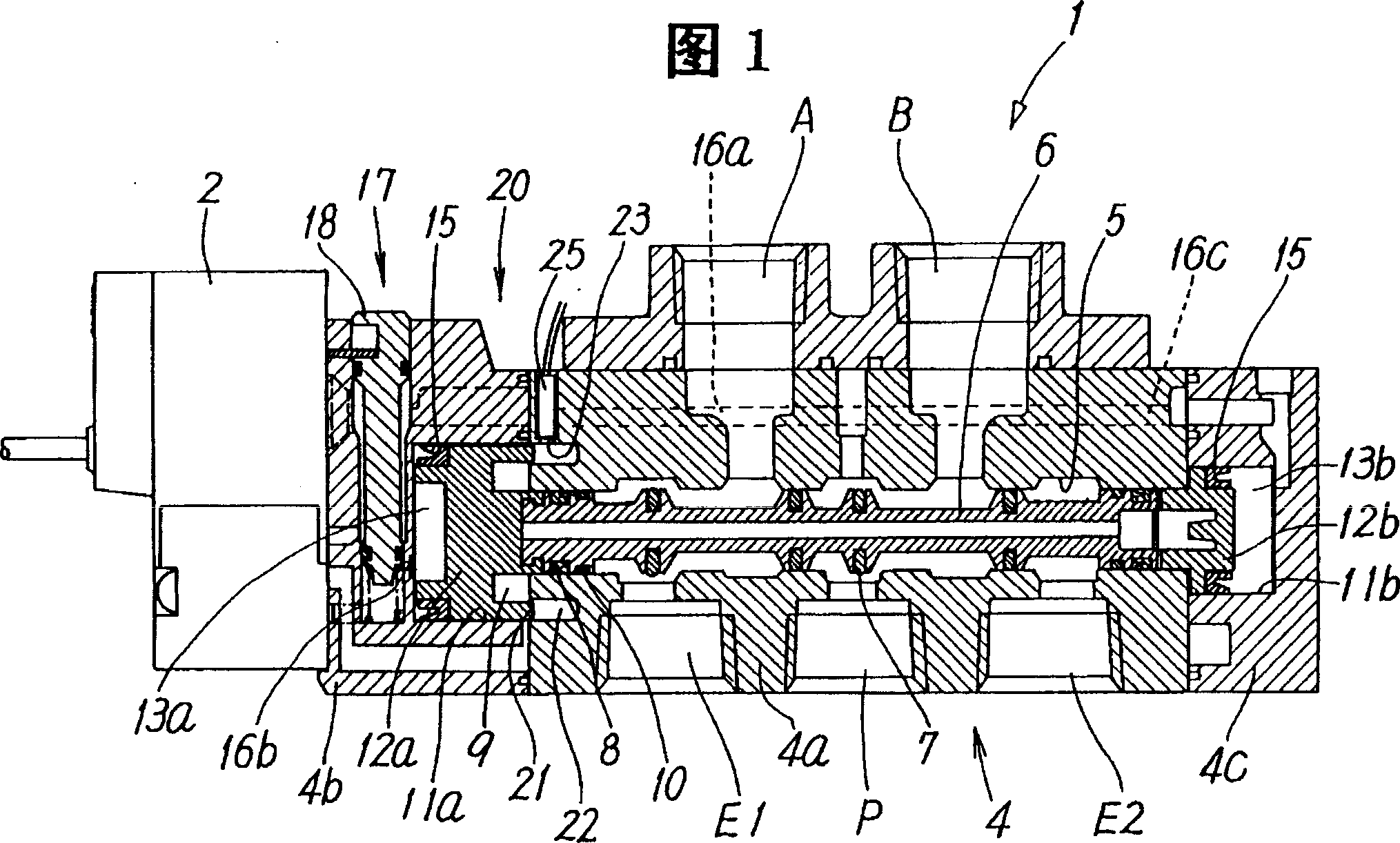
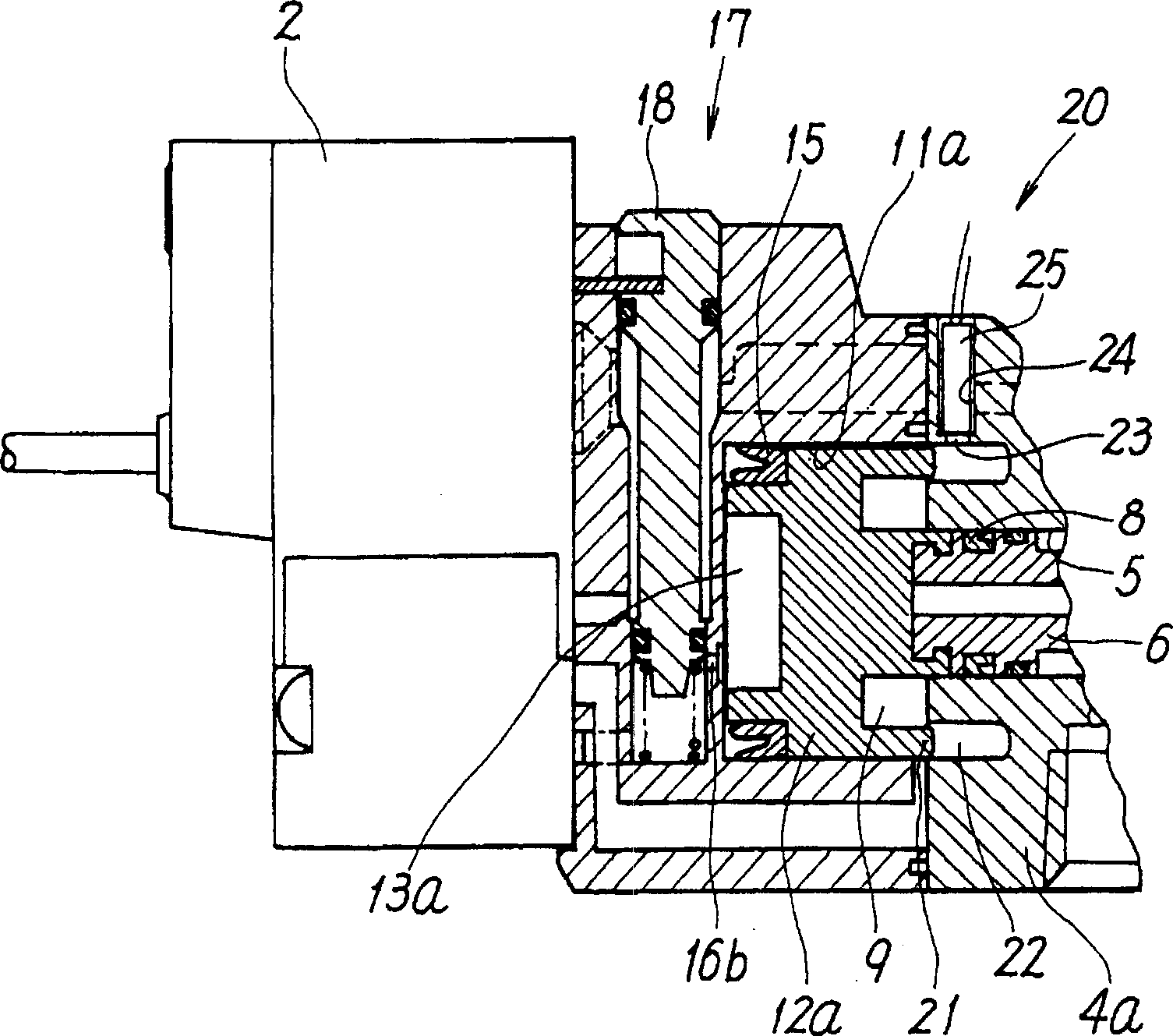
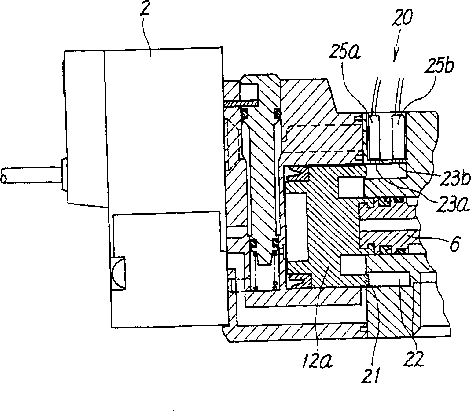
[0019] FIG. 1 shows the first embodiment of the reversing valve of the present invention. The reversing valve illustrated here is a single pilot reversing valve in which a main valve 1 is switched by a pilot valve 2 .

[0020] The above-mentioned main valve 1 has a configuration as a 5-port valve and includes a valve body 4 . This valve body 4 consists of a cube-shaped first member 4a, a second member 4b that is connected to one end and serves as a connector for installing the pilot valve 2, and a second member 4b that is connected to the other end and functions as an end cap. The third member 4c is composed.

[0021] On the upper and lower surface of the first member 4a, a supply port P and two discharge ports E1, E2 are provided, and two output ports A, B are provided on the other surface. Inside the first member 4a, A valve hole 5 is provided in which each of these orifices is opened side by side in the axial direction, and a valve element 6 serving as a valve member for s...


PUM


Abstract

The present invention provides a pilot type switching valve with position detecting function. A detected part 21 is formed in an end face in a side of a respiratory chamber 9 of a piston 12a, also a recessed part 22 fitting the detected part 21 is formed in a wall surface of the respiratory chamber 9 in a casing 4, and a photo-sensor 25 for projecting/receiving light to the detected part 21 through a through hole 23 is set up in a position facing in the recessed part 22 of the casing 4, to detect an operating position of the piston 12a, that is, an operating position of a spool 6 by reflecting light from the detected part 21.

Description

technical field [0001] The present invention relates to a pilot-operated directional control valve with a position detection function capable of detecting the operating position of a valve member such as a valve core by light. Background technique [0002] A reversing valve using a magnet to detect the switching position of the spool is known, for example, in Japanese Patent Application Laid-Open No. 2-66784 (microfilm of Japanese Patent Application No. Sho 63-144027). In this reversing valve, a magnet is installed on the spool, and a magnetic sensor is installed on the valve body at the same time. The magnetic sensor detects the magnet moving together with the spool, thereby detecting the switching position of the spool. [0003] However, the reversing valve of the prior art described in the above-mentioned known documents is because it uses a magnet as a detected object, and relies on a magnetic sensor to detect the magnetic mode from this magnet, so it is easily affected ...

Claims


Application Information

Patent Timeline
IPC IPC(8): F16K37/00F15B13/04F15B15/28F16K13/00F16K31/42
CPCY10T137/86614F15B15/2807Y10T137/8326Y10T137/8663Y10T137/8242F15B13/0402F15B2013/0409F16K13/00
Inventor 林文也石川诚
Owner SMC CORP
Why Eureka
Try Eureka