Shower nozzle device

A shower head and main body technology, applied in the direction of spraying device, liquid spraying device, etc., can solve problems such as instability and shaking, and achieve the effect of operability

Inactive Publication Date: 2020-03-06
LIXIL CORP
View PDF1 Cites 0 Cited by
  • Summary
  • Abstract
  • Description
  • Claims
  • Application Information

AI Technical Summary

Problems solved by technology

In this case, it becomes an unstable operation of pushing in the biased spring, and there is room for improvement in terms of operability.
[0009] In addition, there are problems in that when the push button is in the pushed position, shaking occurs without holding the button cover, or when the shower head is placed in a posture where the push button is down, only the button cover moves.

Method used


Image

  • Shower nozzle device
  • Shower nozzle device
  • Shower nozzle device

Examples


Embodiment Construction

[0081] Hereinafter, an example of a shower head device according to an embodiment of the present invention will be described based on the drawings.

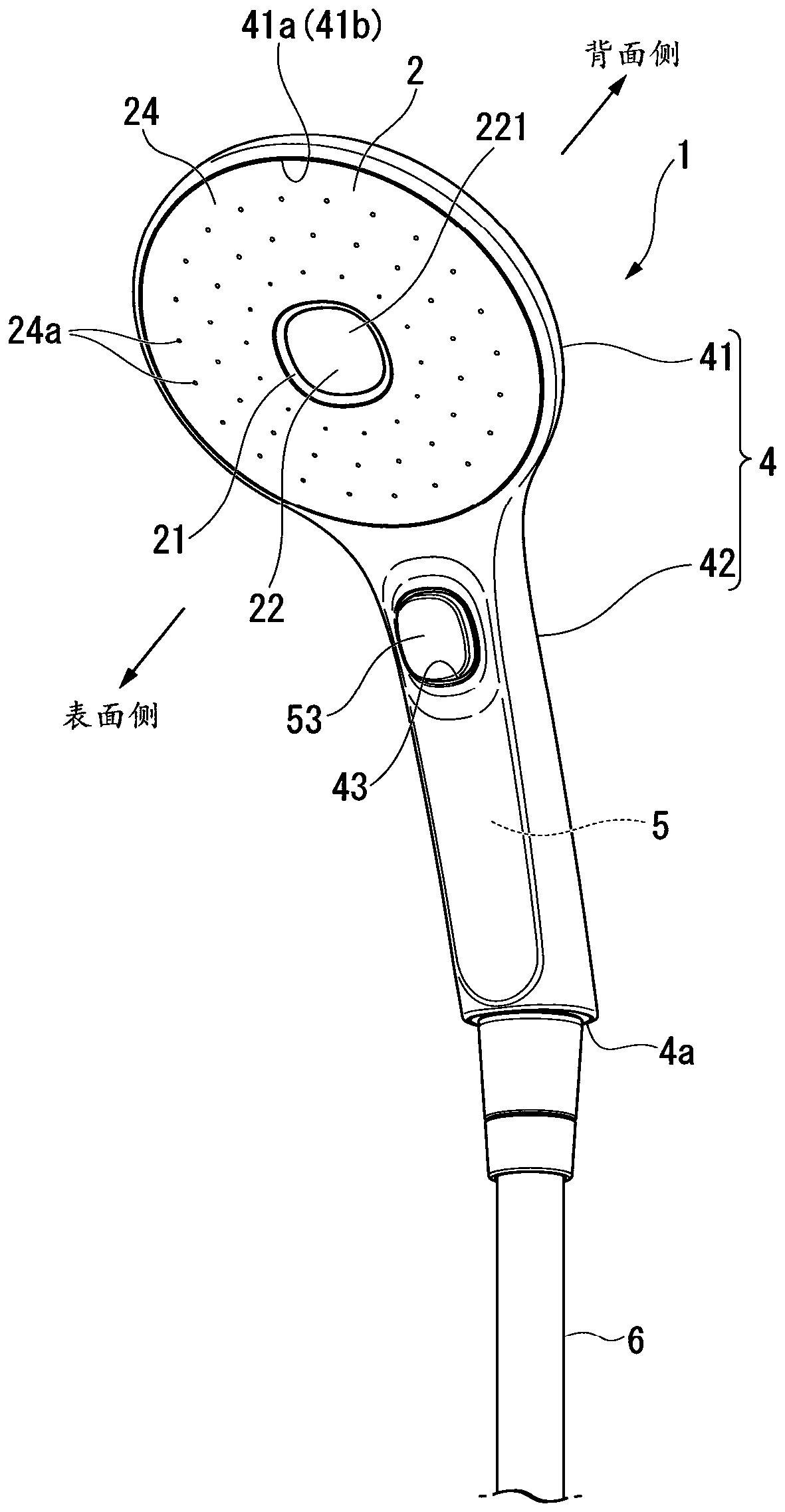
[0082] figure 1 and figure 2 The shower head device 1 of the present embodiment shown is connected to a water supply hose 6 (not shown) extending from a water supply source (not shown). figure 1 ), and a hand shower that sprays fluid such as hot or cold water from the surface side.

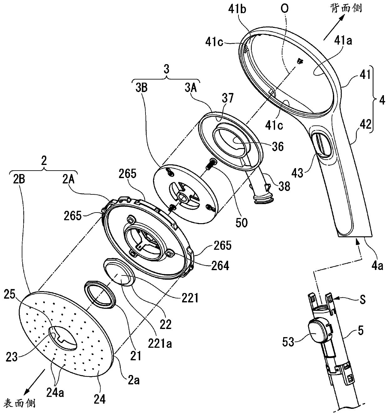
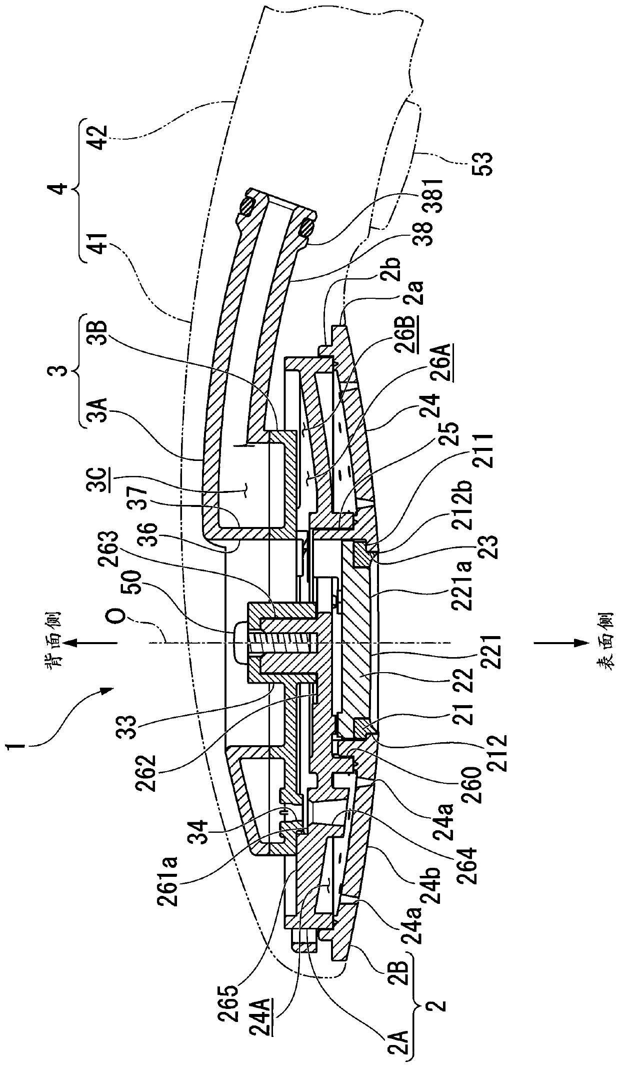
[0083] Such as image 3 As shown, the shower head device 1 is equipped with: a sprinkling part 2, which has a sprinkling hole 24a on the surface and sprinkling fluid; , and the fluid from the upstream side is supplied to the sprinkling part 2; the main body casing 4 accommodates the sprinkling part 2 and the water passing part 3; the temporary water stop mechanism unit 5 (refer to figure 2 ), which is accommodated in the main body casing 4.

[0084] The shower head device 1 has a structure that can be switched from the water supply state to th...


PUM


Abstract

A shower nozzle device includes a main body housing (4) having a nozzle main body portion (41) and a handle portion (42) connected to the nozzle main body portion (41); a temporary water stopping mechanism unit (5), which is integrally provided with a valve core (52) for opening or closing a flow path and capable of temporarily stoppping a fluid flowing in the flow path; a push button (53) which can be assembled with respect to the temporary water stopping mechanism unit (5), and used for opening and closing moving the valve core (52). The handle portion (42) of the main body housing (4) has astorage portion capable of accommodating the temporary water stopping mechanism unit (5), and a handle opening portion (4a) into which the temporary water stopping mechanism unit (5) can be insertedis formed at an end of a side opposite to the nozzle main body portion (41).

Description

technical field [0001] The present invention relates to shower head devices. Background technique [0002] A conventional shower head device is connected to a water supply hose extending from a water supply source, and sprays fluid such as hot water from the surface side. Such a shower head device includes: a sprinkler plate having a sprinkler hole on the surface; and a main body housing which holds the sprinkler plate and has a water passage communicating with the sprinkler hole inside. [0003] For example, there is a device described in Patent Document 1, which includes: a main body housing having a sprinkling part and a handle connected to the sprinkling part; And can temporarily stop the fluid circulating in the flow path; press the button, which is arranged to be able to be assembled with respect to the temporary water stop mechanism unit, and is used to make the valve core open and close; The core performs an opening and closing operation to open and close the flow ...

Claims


Application Information

Patent Timeline
IPC IPC(8): B05B7/04B05B7/26B05B13/02B05B15/00B05B12/04B05B12/00B05B15/63
CPCB05B7/0425B05B7/265B05B12/002B05B12/04B05B13/0278B05B15/00B05B15/63
Inventor 中田浩司坂田真也
Owner LIXIL CORP
Why Eureka
Try Eureka