Least square migration imaging method and device based on L-BFGS algorithm

A technology of L-BFGS and least squares, which is applied in the field of geophysical exploration, can solve problems such as inability to obtain imaging results, insufficient imaging accuracy, and slow convergence speed, and achieve the effect of accelerating the inversion convergence speed, fast convergence, and stable convergence

Active Publication Date: 2020-03-17
CHINA PETROLEUM & CHEM CORP +1
View PDF6 Cites 5 Cited by
  • Summary
  • Abstract
  • Description
  • Claims
  • Application Information

AI Technical Summary

Problems solved by technology

[0005] The technical problem to be solved by the present invention is that the imaging precision of the existing imaging technology in seismic exploration is not enough, and there is still a slow convergence speed in the nonlinear optimization problem solving method in the imaging process, and the optimal imaging result cannot be obtained

Method used


Image

  • Least square migration imaging method and device based on L-BFGS algorithm
  • Least square migration imaging method and device based on L-BFGS algorithm
  • Least square migration imaging method and device based on L-BFGS algorithm

Examples


Embodiment 1

[0054] In order to solve the technical problems existing in the prior art, an embodiment of the present invention provides a least squares migration imaging method based on the L-BFGS algorithm.

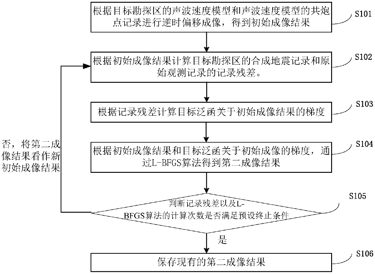
[0055] figure 1 It is a flow chart of the steps of the least squares migration imaging method based on the L-BFGS algorithm in Embodiment 1 of the present invention; the real-time example of the least squares migration imaging method based on the L-BFGS algorithm in the present invention includes the following steps.

[0056] Step S101, the initial imaging result acquisition step

[0057] According to the acoustic wave velocity model of the target exploration area and the common shot point records of the acoustic wave velocity model, reverse time migration imaging is performed to obtain the initial imaging results.

[0058] Specifically, Fourier transform is first performed on the common shot point record of the acoustic wave velocity model of the target exploration area to obtain t...

Embodiment 2

[0083] In order to solve the technical problems existing in the prior art, an embodiment of the present invention provides a least squares migration imaging device based on the L-BFGS algorithm.

[0084] The least squares offset imaging device based on the L-BFGS algorithm in this embodiment includes a computer-readable storage medium storing a computer program. When the computer program is executed by a processor, the least squares offset imaging device based on the L-BFGS algorithm in Embodiment 1 All steps in the imaging method.

[0085] It should be noted that, for specific implementation steps of the least squares migration imaging method based on the L-BFGS algorithm, refer to Embodiment 1, which will not be repeated here.

[0086] Applying the least squares migration imaging method based on the L-BFGS algorithm provided by the embodiment of the present invention, by introducing the optimal solution method of L-BFGS, avoiding the optimization process from falling into th...


PUM


Abstract

The invention discloses a least square migration imaging method and device based on an L-BFGS algorithm. The method comprises steps of performing reverse time migration imaging according to an acoustic velocity model of a target exploration area and a common shot point record of the acoustic velocity model to obtain the initial imaging result; calculating record residual errors of the synthetic seismic record and the original observation record of the target exploration area according to the initial imaging result; calculating the gradient of a target functional relative to the initial imagingresult according to the record residual error; obtaining the second imaging result through an L-BFGS algorithm according to the initial imaging result and the gradient of the target functional with respect to the initial imaging result; and judging whether the record residual error and the calculation frequency of the L-BFGS algorithm meet a preset termination condition or not. The method is advantaged in that the optimal solution method of the L-BFGS is introduced, so the optimization process is prevented from falling into local optimization in the solving process of a nonlinear optimizationproblem, and the optimization process in the aspect of nonlinear optimization is more stable.

Description

technical field [0001] The invention relates to the technical field of geophysical exploration, in particular to a least squares migration imaging method and device based on an L-BFGS algorithm. Background technique [0002] At present, with the improvement of the demand for seismic exploration, the accuracy of underground structure imaging has correspondingly higher requirements. The existing traditional reverse time migration technology can perform relatively accurate imaging of complex subsurface structures, but it still cannot meet the high-fidelity imaging requirements of complex oil and gas reservoirs. In the prior art, the least squares reverse time migration imaging technology is often used. It is based on the inversion theory. It mainly establishes the relationship between the reflection coefficient and the seismic record function, and continuously iterates the imaging results, so that based on the imaging results The residual error between the demigration syntheti...

Claims


Application Information

Patent Timeline
Patent Type & Authority Applications(China)
IPC IPC(8): G01V1/36
CPCG01V1/36G01V2210/51
Inventor 陶永慧段心标
Owner CHINA PETROLEUM & CHEM CORP
Why Eureka
Try Eureka