
A Simulation Method for Imaging Dynamic Ellipticity of Optical Remote Sensing Camera

A technology of optical remote sensing and simulation methods, applied in design optimization/simulation, sustainable transportation, etc., can solve the problem of inability to effectively evaluate the imaging performance of optical systems, and achieve the effect of accurate simulation analysis results

Active Publication Date: 2022-06-07
CHANGCHUN INST OF OPTICS FINE MECHANICS & PHYSICS CHINESE ACAD OF SCI
View PDF6 Cites 0 Cited by
  • Summary
  • Abstract
  • Description
  • Claims
  • Application Information

AI Technical Summary

Problems solved by technology

[0006] Aiming at the problem that the existing point spread function (PSF) ellipticity analysis mainly focuses on static ellipticity analysis and cannot effectively evaluate the imaging performance of the optical system, the embodiment of the present invention provides a dynamic ellipticity method for optical remote sensing camera imaging simulation method

Method used


Image

  • A Simulation Method for Imaging Dynamic Ellipticity of Optical Remote Sensing Camera
  • A Simulation Method for Imaging Dynamic Ellipticity of Optical Remote Sensing Camera
  • A Simulation Method for Imaging Dynamic Ellipticity of Optical Remote Sensing Camera

Examples


Embodiment Construction

[0037] In order to enable those skilled in the art to better understand the solutions of the present invention, the technical solutions in the embodiments of the present invention will be clearly and completely described below in conjunction with the drawings in the embodiments of the present invention. Obviously, the described embodiments are only It is an embodiment of a part of the present invention, but not all embodiments. Based on the embodiments of the present invention, all other embodiments obtained by persons of ordinary skill in the art without making creative efforts shall fall within the protection scope of the present invention.

[0038] The terms "first", "second", "third", "fourth", etc. (if any) in the description and claims of the present invention and the above drawings are used to distinguish similar objects and not necessarily Describe a specific order or sequence. It is to be understood that the terms so used are interchangeable under appropriate circums...


PUM


Abstract

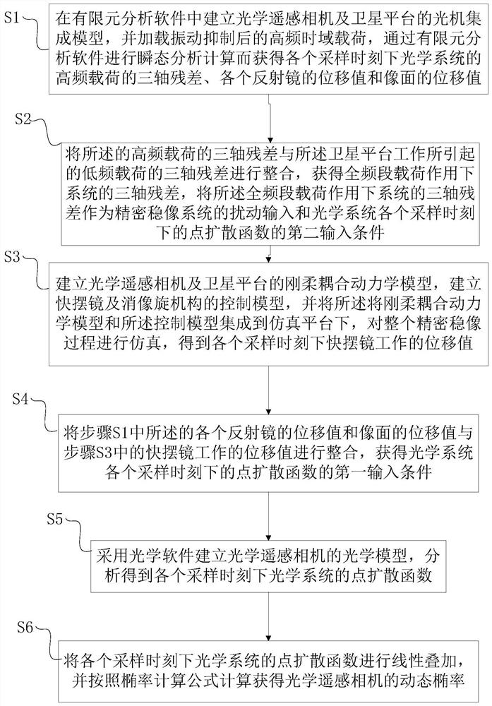
The embodiment of the invention discloses a method for simulating the dynamic ellipticity of imaging by an optical remote sensing camera. The simulation method can be summarized as four steps: integrated simulation analysis of micro-vibration in time domain, integrated simulation analysis of precise image stabilization, linear superposition of point spread function (PSF) and calculation of ellipticity of point spread function (PSF). This simulation method integrates the three disciplines of optics, mechanics, and control, and can comprehensively consider the coupling effects between different disciplines, which is closer to the real working process of optical remote sensing cameras. The evaluation of optical system imaging performance has stronger guiding significance.

Description

technical field [0001] The invention relates to the technical field of optical remote sensing imaging, in particular to a simulation method for imaging dynamic ellipticity of an optical remote sensing camera. Background technique [0002] With the increasing demand for astronomical observation and military and civilian earth observation, optical remote sensing cameras are developing in the direction of large aperture, large field of view and high image quality. In order to ensure that the imaging quality of the optical remote sensing camera meets the index requirements in the working state, considering that the optical remote sensing camera often has the characteristics of long working time and long exposure time, it is necessary to consider that when the structure of the optical remote sensing camera is disturbed by various environments within a certain period of time, the optical System imaging performance. At present, dynamic ellipticity analysis is a good evaluation met...

Claims


Application Information

Patent Timeline
Patent Type & Authority Patents(China)
IPC IPC(8): G06F30/20
CPCY02T90/00
Inventor 赵阳李晓波杨勋姜禹希
Owner CHANGCHUN INST OF OPTICS FINE MECHANICS & PHYSICS CHINESE ACAD OF SCI
Learn More