Cooling fan drive circuit and cooking utensil

A driving circuit and cooling fan technology, which is applied in the direction of machines/engines, pump control, non-variable pumps, etc., can solve the problem of cooling fans occupying more MCU resources, and achieve the effect of reducing noise and improving user experience

Active Publication Date: 2020-04-10
GREE ELECTRIC APPLIANCES INC
View PDF9 Cites 1 Cited by
  • Summary
  • Abstract
  • Description
  • Claims
  • Application Information

AI Technical Summary

Problems solved by technology

[0004] The invention provides a cooling fan drive circuit and a cooking utensil to solve the problem that more MCU resources need to be occupied for the existing cooling fan speed adjustment control

Method used


Image

  • Cooling fan drive circuit and cooking utensil
  • Cooling fan drive circuit and cooking utensil
  • Cooling fan drive circuit and cooking utensil

Examples


Embodiment Construction

[0033] Exemplary embodiments of the present disclosure will be described in more detail below with reference to the accompanying drawings. Although exemplary embodiments of the present disclosure are shown in the drawings, it should be understood that the present disclosure may be embodied in various forms and should not be limited by the embodiments set forth herein. Rather, these embodiments are provided for more thorough understanding of the present disclosure and to fully convey the scope of the present disclosure to those skilled in the art.

[0034] Those skilled in the art can understand that, unless otherwise defined, all terms (including technical terms and scientific terms) used herein have the same meaning as commonly understood by those of ordinary skill in the art to which this invention belongs. It should also be understood that terms, such as those defined in commonly used dictionaries, should be understood to have meanings consistent with the meanings in the co...


PUM


Abstract

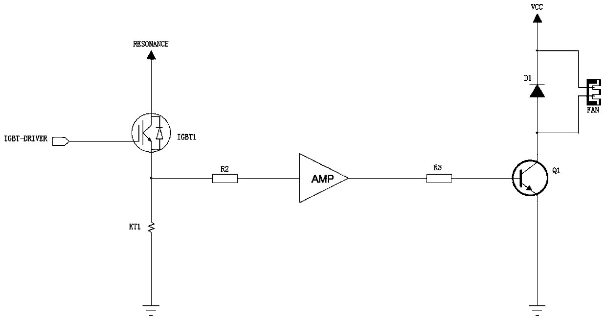
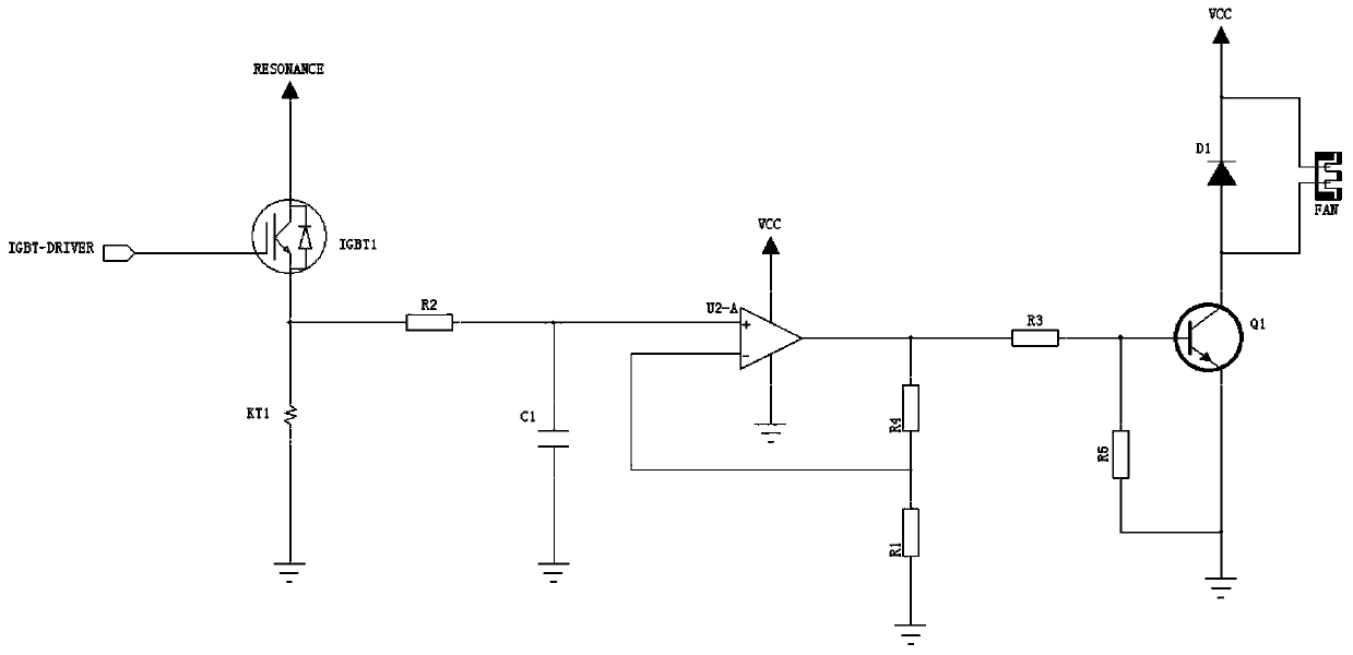
The invention discloses a cooling fan drive circuit and a cooking utensil. The cooling fan drive circuit comprises a current sampling circuit, a signal amplification circuit and a drive circuit body which are connected in sequence. The current sampling circuit is used for detecting real-time currents of a heating device in the heating process. The signal amplification circuit is used for conducting signal amplification on the real-time currents detected by the current sampling circuit. The drive circuit body is used for controlling the rotating speed of a cooling fan according to current signals output by the signal amplification circuit. According to the cooling fan drive circuit and the cooking utensil, the fan can be driven with the help of the current sampling signals, the number of temperature wrap sampling circuits can be decreased, MUC resource consumption is reduced, power dissipation is also reduced, and meanwhile the rotating speed of the fan can be adjusted.

Description

technical field [0001] The invention relates to the technical field of power electronics, in particular to a cooling fan drive circuit and a cooking utensil. Background technique [0002] The cooling fan driving method of the traditional electromagnetic cooking appliance is usually controlled by using an MCU to output a switch signal. However, this cooling fan driving method can only realize two states of on and off, and cannot realize adjustable speed, and the control is not intelligent enough. [0003] In order to realize the adjustable speed of the cooling fan, the existing technology uses a temperature sensor package and MUC to sample the temperature of the cooling device, find the corresponding speed according to the collected temperature, and control the fan speed. Although this method can adjust the speed, the It needs to occupy more MCU resources, and the user experience is poor. Contents of the invention [0004] The invention provides a cooling fan drive circui...

Claims


Application Information

Patent Timeline
Patent Type & Authority Applications(China)
IPC IPC(8): F04D27/00
CPCF04D27/004
Inventor 邱健唐军荣周世燕夏乙珩
Owner GREE ELECTRIC APPLIANCES INC
Why Eureka
Try Eureka