Heating device and temperature controlled spray assembly
A technology for spraying components and temperature control, which is applied to parts of connecting devices, spraying devices, coupling devices, etc., and can solve problems such as increasing costs
Active Publication Date: 2020-04-14
PIOTECH CO LTD
12 Cites 1 Cited by
AI-Extracted Technical Summary
Problems solved by technology
In this regard, the known solution is to incorporate a filter that can suppress radio frequency signals in the electrical circuit of t...
Method used
[0029] In this embodiment, the side of the gas inlet portion 102 is provided with a plate 110 or flange which can bear against a support structure (not shown) at the top of the reaction chamber. The plate 110 is also provided with a fixing means 111 for fixing the shower assembly 100 on the top of the cavity. There is a space between the plate 110 and the lateral extension of the gas distribution part 103 below, and this space reduces the contact with the cavity when the shower assembly 100 is fixed in the cavity, so as to reduce heat loss. The shower assembly 100 also has at least one channel 112 for accommodating at least one heating wire (as shown in FIG. 4 ), which extends in the gas inlet portion 102 and the gas distribution portion 103 . In this embodiment, the channel 112 extends downward from one side of the gas inlet part 102 and a place above the plate 110 and turns to extend laterally at the gas distribution part 103 and surrounds the gas distribution part 103 at the most end to approach the gas distribution part 103...
Abstract
The invention discloses a heating device, which is applied to a plasma treatment semiconductor manufacturing device. The heating device comprises at least one heating wire extending in a coverage range of a radio frequency signal, a power supply used for providing a power signal to the at least one heating wire, and a temperature controller used for controlling the power supply at least based on adefault temperature. The at least one heating wire is covered by at least one shielding assembly and used for shielding the radio frequency signal so as to prevent the radio frequency signal from being electrically coupled to the at least one heating wire, the power supply and the temperature controller.
Application Domain
Coupling device detailsSpray nozzles
Technology Topic
PhysicsPlasma treatment +6
Image
Examples
- Experimental program(1)
Example Embodiment
[0021] In the following detailed descriptions of several exemplary embodiments, reference is made to the accompanying drawings, which form part of the present invention. And it is shown by way of example description, by which the described specific embodiments can be implemented. Sufficient details are provided to enable those skilled in the art to implement the specific embodiments, and it should be understood that other specific embodiments can be used and other changes can be made without departing from the spirit or scope thereof. In addition, although this may be the case, the reference to "a specific embodiment" does not necessarily belong to the same or singular specific embodiment. Therefore, the following detailed description does not have a limiting idea, and the scope of the specific embodiments of the description is only defined by the scope of additional patent applications.
[0022] In the entire specification and the scope of the claims, unless otherwise clearly stated in the context, the following terminology has the meaning clearly associated with this. When used here, unless expressly stated otherwise, the term "or" is an inclusive usage of "or" and is equivalent to the term "and/or". Unless clearly stated otherwise in the context, the term "based" is not exclusive and allows to be based on most other factors not described. In addition, in the overall application, the meanings of "one", "one" and "the" include plural references. The meaning of "in" includes "in" and "on".
[0023] The following is a brief summary of these innovative themes to provide a basic understanding of some aspects. This short description is not expected to be a complete overview. This short description is not expected to be used to identify the main or key components, or to describe or narrow the scope. Its purpose is only to present certain concepts in a brief form as a prelude to the more detailed description presented later.
[0024] The present invention proposes an electric heating device that has electric heating capability and can accommodate a radio frequency electric field without a filter. It can be located in the spray assembly of the semiconductor device or in the heating plate of the substrate support. . The heating device has integrated shielding components and heating wires, and casting is inside. This design can reduce the cost of hard equipment and the volume of hard equipment, and has application value for any kind of electric heater that requires high temperature response and is accompanied by radio frequency introduction.
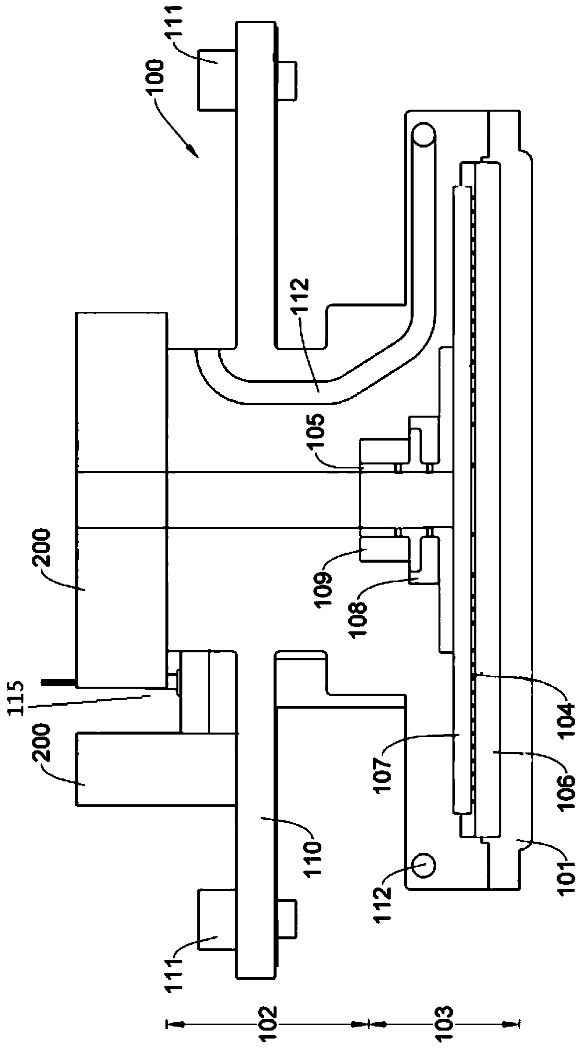
[0025] figure 1 An embodiment of a shower assembly 100 and its connecting component 200 of the present invention is shown. The spray assembly 100 is disposed above a reaction chamber (not shown), and a bottom of the spray assembly 100 is used as a top of the reaction area, and a top of the spray assembly 100 is connected with various connecting parts 200 to make the spray The component 100 is coupled to other external devices (not shown), such as a radio frequency signal source, a cooling device, and a gas supply source.
[0026] The radio frequency signal source is electrically coupled to an electrode in the shower assembly 100, such as the shower plate 101, through a cable, so that the radio frequency signal is transmitted to the reaction chamber via the shower plate 101. The cooling device provides a cooling mechanism in the spray assembly 100 to cool the spray assembly 100. It is like cooling water or coolant flowing into a predetermined pipe. The gas supply source can provide one or more gases or mixed gases to multiple gas chambers and ducts in the spray assembly 100, which are heated by the spray assembly 100 and discharged. With the control of the valve, the gas flow rate from the gas supply source can be adjusted.
[0027] The shower assembly 100 basically includes a gas inlet portion 102 and a gas distribution portion 103. The gas inlet portion 102 has a gas inlet channel extending downward from the top for receiving reaction gas from a gas supply source. The gas distribution part 103 is located below the gas inlet part 102 and defines a plurality of gas chambers. As shown in the figure, the gas distribution part 103 also has a porous layer 104 and a confluencer 105 from above the shower plate 101. The shower plate 101 and the porous layer 104 define a gas chamber 106, the porous layer 104 and the confluencer 105 define a gas chamber 107, and the inner wall of the confluencer 105 and the gas distribution part 103 define two gas chambers 108 and 109. The confluencer 105 has a gas inlet passage communicating with the gas inlet passage of the gas inlet portion 102.
[0028] In one embodiment, the gas inlet channel receives an inert gas. The gas chambers 108 and 109 on both sides of the manifold 105 receive a first and a second reaction gas through other channels (not shown in this figure), and mix them with the inert gas in the inlet channel through the holes of the manifold 105, and sequentially Enter the air chamber 107 and the air chamber 106. When the gas enters from the gas inlet portion 102 and flows through the gas chambers of the gas distribution portion 103, it can be sufficiently heated by the gas inlet portion 102 and/or the gas distribution portion 103, and is finally released into the reaction area. In other embodiments, the gas distribution portion 103 can be arranged in different ways, which is not limited by the foregoing examples.
[0029] In this embodiment, the side of the gas inlet portion 102 is provided with a plate 110 or flange, which can support a supporting structure (not shown) on the top of a reaction chamber. The plate 110 is also provided with a fixing means 111 to fix the spray assembly 100 on the top of the cavity. There is a space between the plate 110 and the horizontal extension of the gas distribution portion 103 below it, and this space reduces the contact with the cavity when the shower assembly 100 is fixed to the cavity, so as to reduce heat loss. The spray assembly 100 also has at least one heating wire (such as Figure 4 (Shown) at least one channel 112, which extends in the gas inlet portion 102 and the gas distribution portion 103. In this embodiment, the channel 112 extends downward from one side of the gas inlet portion 102 and above the plate 110, and is transformed into a lateral extension at the gas distribution portion 103 and surrounds the gas distribution portion 103 at the end to be close to The periphery of the air chamber 106 and the air chamber 107. In another embodiment, it can be implemented as more channels 112. In some embodiments, the channel 112 may spiral downward.
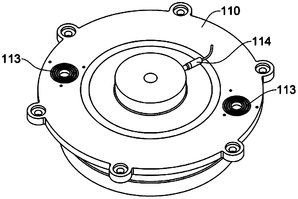
[0030] figure 2 The top of the spray assembly 100 is shown without the connecting part 200. As shown in the figure, the periphery of the board 110 is provided with a plurality of holes of the aforementioned fixing means 111. In addition, the board 110 is also provided with holes 113 for installing a thermal couple, such as image 3 Shown. One side of the top of the gas inlet portion 102 is provided with a connector 114 of the heating wire, and the other end is connected to a power supply (not shown) that provides power signals to the heating wire. The power supply gas is electrically connected to a temperature controller (not shown). The temperature controller controls the power supply based on at least a default temperature. At least the heating wire, the power supply and the temperature controller constitute an electric heating device, which can break through the temperature limit of the oil heater.
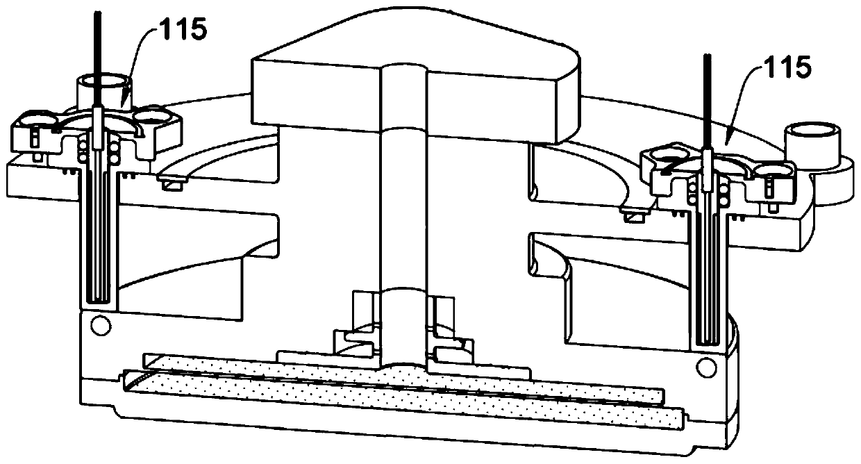
[0031] image 3 Another cross-sectional view of the shower assembly 100 and the connecting component 200 is shown. The two thermocouples 115 are respectively held in the holes 113 and extend downward until they contact a top surface of the gas distribution part 103. The other end of the thermocouple 115 is electrically connected to the temperature controller to input the read temperature data of the shower assembly 100 to the temperature controller. Therefore, the temperature controller can control the power supply to provide power signals to the heating wires according to a default temperature and the received temperature data. In a possible embodiment, the thermocouple 115 can be replaced by any other temperature sensor to measure the temperature of the shower assembly 100 or its electrode position. The temperature controller can also control the aforementioned cooling device to lower the temperature of the spray assembly. In an embodiment, one of the two thermocouples 115 may be configured for temperature control, and the other may be configured for high temperature alarm.
[0032] Figure 4 Showing a partial cross-sectional view of an embodiment of the present invention, the heating device has a heating wire 400 and a shielding component 500. Figure 5 display Figure 4 Of a cross-sectional view. In this embodiment, the heating wire 400 is wrapped in the shielding component 500, and the shielding component 500 is at least partially wrapped in a thermally conductive layer 600. The heating wire 400 has two terminals 401 and 402 that receive power signals from the power supply. A connector 700, such as figure 2 The connector 114 shown covers the terminals 401 and 402 of the heating wire 400 and the end of the shielding assembly 500.
[0033] Along as figure 1 As shown in the passage 112, the heating wire 400 extends in the gas inlet portion 102 and the gas distribution portion 103 of the shower assembly 100, and the shielding assembly 500 is located between the heating wire 400 and the gas inlet portion 102 and the gas distribution portion 103 to protect The heating wire 400 is structurally separated from the spray assembly 100. The heat conducting layer 600 surrounding the shielding assembly 500 is configured to receive heat from the heating wire 400 and transfer the heat to various parts of the shower assembly 100 through the surface contact with the gas inlet portion 102 and the gas distribution portion 103, such as a shower Plate 101 or electrode.
[0034] In this embodiment, the shielding assembly 500 has a double-layer structure, and includes a first shielding portion composed of a first metal layer 501 and a first heat-resistant layer 502, and a second metal layer 503 and a second The heat-resistant layer 504 constitutes a second shielding portion. This double-layer structure is for the convenience of casting. In order to cast the first metal layer 501 into the thermal conductive layer 600 and separate it from the thermal conductive layer 600, it is necessary to increase the second heat-resistant layer 504 for electrical insulation. However, since the second heat-resistant layer 504 is a material that cannot be cast, a second metal layer 503 is provided for filling the second heat-resistant layer 504.
[0035] The first shielding part covers the second shielding part. The first heat-resistant layer 502 covers the heating wire 400, and the first metal layer 501 covers the first heat-resistant layer 502. The second heat-resistant layer 504 covers the first metal layer 501, and the second metal layer 503 covers the second heat-resistant layer 504. The thermally conductive layer 600 covers the second metal layer 503. In principle, the first shielding portion is sufficient to achieve the shielding effect, so the first metal layer 501 is grounded 506. In some possible embodiments, the second metal layer 503 may be grounded, or the second shielding portion may be omitted, and an electrically insulating layer separates the thermal conductive layer 600 and the first metal layer 501.
[0036] The joint 700 can be filled with the same material as the heat-resistant layers 502 and 504. The material of the heating wire 400 can be nickel, nickel-chromium alloy or the like, which can be heated to 200°C or above. The metal layers 501 and 503 may be stainless steel or similar materials. The heat-resistant layers 502 and 504 may be magnesium oxide, aluminum oxide, zirconium oxide, aluminum nitride or similar substances. Known casting methods and material filling can be used to realize the above configuration. The thickness of the thermal conductive layer 600 is sufficient to meet the principle of mechanical strength. The heat-resistant layers 502, 504 are mainly used to insulate RF hot, so the thickness of the heat-resistant layers 502, 504 depends on the RF power. In one embodiment, the thickness of the metal layers 501 and 503 is about 1 mm, and the thickness of the heat-resistant layers 502 and 504 is about 2 mm. In other feasible embodiments, more or fewer shielding components or shielding layers may be included, and at least a part of these shielding components may be selected to be grounded.
[0037] The heat generated by the heating wire 400 receiving the power signal is transferred to the thermal conductive layer 600 contacting the shower assembly 100 through the shielding assembly 500. according to figure 1 As shown in the channel 112 path, one side of the gas inlet 102 of the shower assembly 100 can be heated, and a lateral extension and outer edge of the gas distribution portion 103 can be heated, so the gas is mainly in the gas chamber of the gas distribution portion 103 Medium is heated. In other embodiments, the gas may be heated in the first stage at the gas inlet portion 102 and heated in the second stage at the gas distribution portion 103.
[0038] Generally speaking, the radio frequency signal is transmitted from above the shower assembly 100 to the shower plate 101, and the range of the radio frequency signal covers the heating wire 400 in the channel 112. Since the shielding component 500 covers the heating wire 400 extending in the channel 112, the radio frequency signal is shielded by the double-layer shielding portion, and the radio frequency signal is not coupled to the heating wire 400, thereby avoiding interference with the circuit of the heating device. Moreover, since the radio frequency signal does not enter the heating circuit, there is no need to include a radio frequency filter in the circuit. Therefore, the spray assembly and heating device provided by the present invention can save the cost of configuring the radio frequency filter and save the occupied space of the radio frequency filter.
[0039] The above content provides a complete description of the manufacture and use of the combination of the described specific embodiments. Because many specific embodiments can be produced without departing from the spirit and scope of this description, these specific embodiments will exist in the scope of the patent applications appended below.
PUM


Description & Claims & Application Information
We can also present the details of the Description, Claims and Application information to help users get a comprehensive understanding of the technical details of the patent, such as background art, summary of invention, brief description of drawings, description of embodiments, and other original content. On the other hand, users can also determine the specific scope of protection of the technology through the list of claims; as well as understand the changes in the life cycle of the technology with the presentation of the patent timeline. Login to view more.