Municipal road overspeed warning system

A technology for municipal roads and warning lights, which is applied to traffic control systems, traffic control systems, instruments and other directions of road vehicles, can solve the problems of wasting electricity, lack of driver's attention, waste of electricity, etc., to save current and reduce losses , the effect of saving electricity

Pending Publication Date: 2020-04-17
王业宏
View PDF11 Cites 3 Cited by
  • Summary
  • Abstract
  • Description
  • Claims
  • Application Information

AI Technical Summary

Problems solved by technology

[0003] Existing speed limit warnings usually use traffic sign prompts or warning lights to continuously flash to indicate that this area needs to slow down, but due to the static display of traffic signs, the driver does not pay enough attention to them, and the drive

Method used


Image

  • Municipal road overspeed warning system
  • Municipal road overspeed warning system
  • Municipal road overspeed warning system

Examples


Embodiment 1

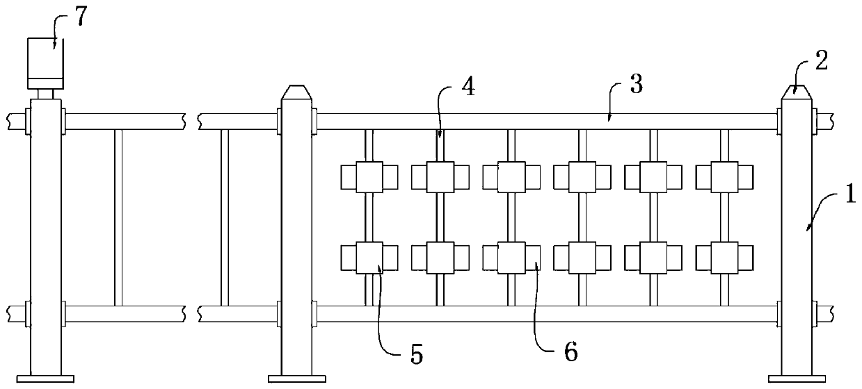
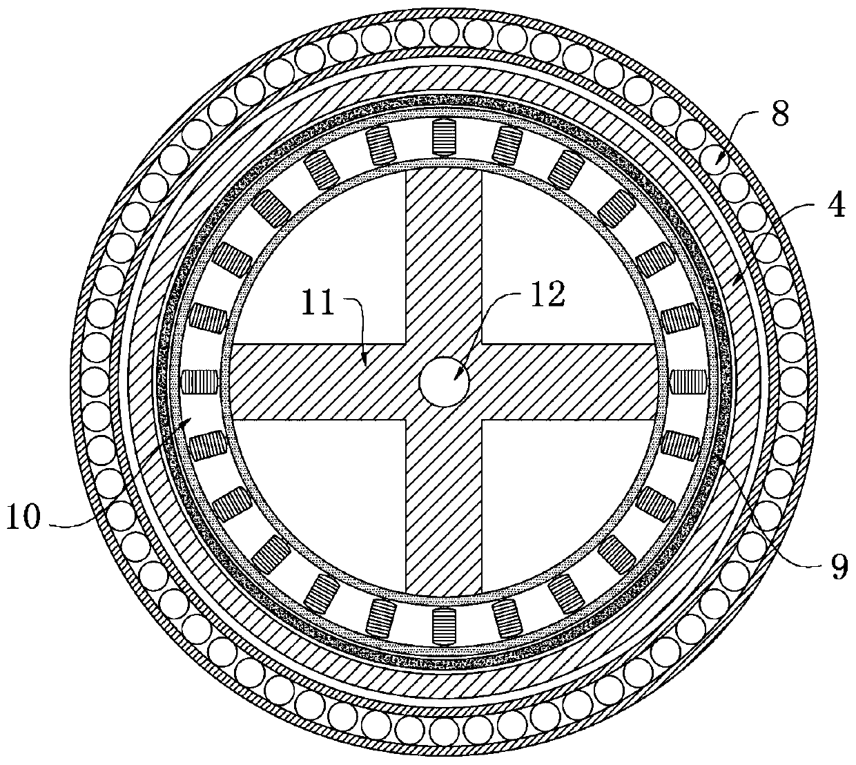
[0029] refer to Figure 1-3 , a municipal road overspeed warning system, comprising a plurality of guardrail support columns 1, wherein a warning light 7 is fixedly installed on the upper end of one of the guardrail support column 1, and a reflective seat 2 is fixedly installed on the upper ends of the remaining plurality of guardrail support columns 1. Two connecting railings 3 are symmetrically installed between the two guardrail support columns 1, and a plurality of reinforcing pipes 4 are equidistantly installed between the two connecting railings 3, and the outer wall of each reinforcing pipe 4 is fixedly sleeved with a bearing 8, each The outer walls of the bearings 8 are fixedly provided with an electromagnetic fan blade mechanism, the inner wall of the reinforcement pipe 4 is fixedly installed with an insulating sleeve 9, and the inner wall of the insulating sleeve 9 is fixedly inserted with a stator winding 10, and the lower end of the stator winding 10 is fixedly inst...

Embodiment 2

[0039] refer to Figure 4 , a municipal road speeding warning system, which is basically consistent with Embodiment 1, the difference is that:

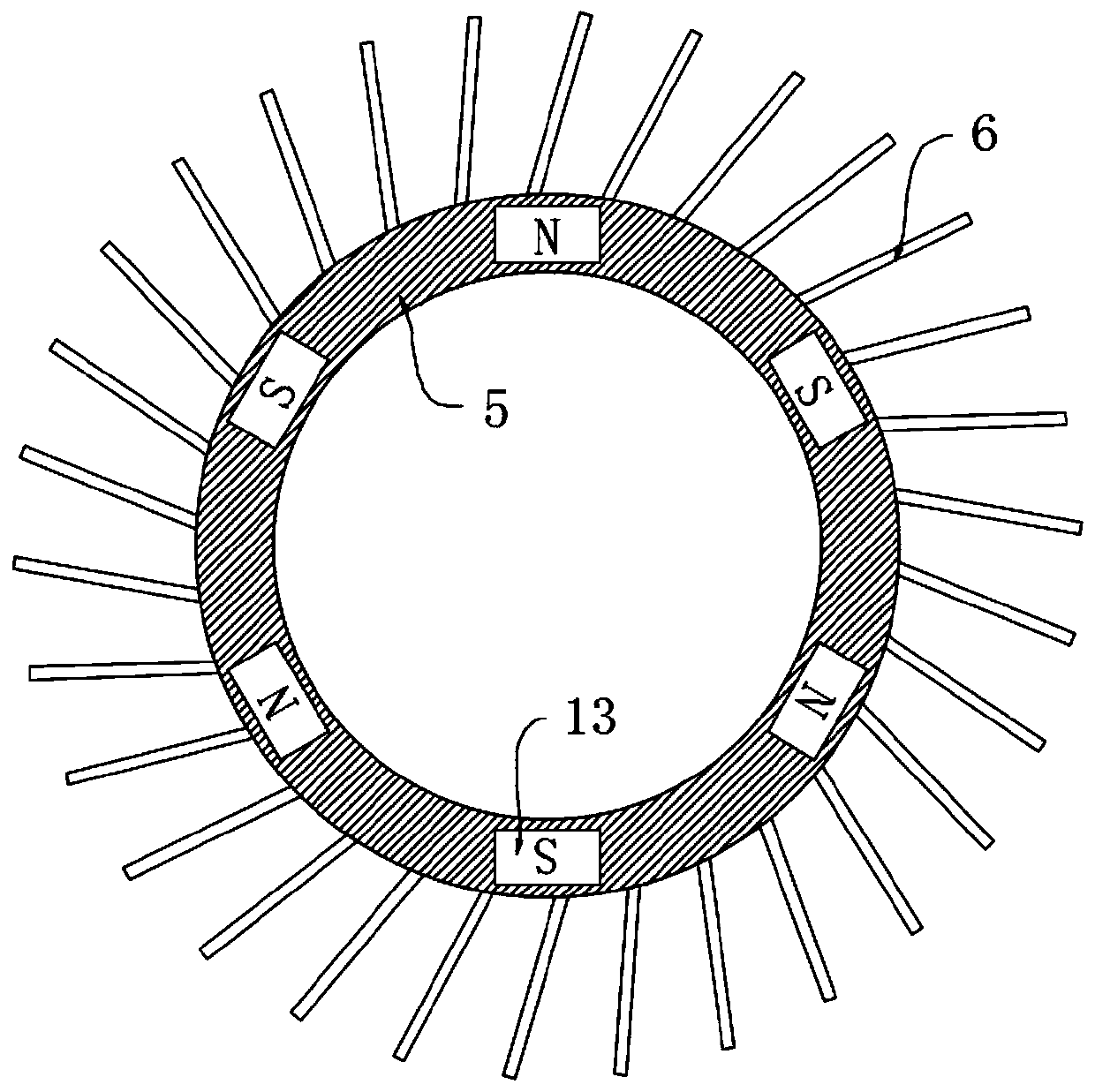
[0040] A plurality of column lamps 14 are installed on the connecting railing 3, and the lower ends of the column lamps 14 are respectively connected with a plurality of reinforcement pipes 4. The distance between the plurality of column lamps 14 and the plurality of electromagnetic blade mechanisms is about 60 meters, and the plurality of column lamps The lamps 14 are respectively electrically connected to a plurality of electromagnetic fan blade mechanisms on the plurality of reinforcement tubes 4;

[0041] When the vehicle passes through a plurality of electromagnetic fan mechanism areas, according to the passing time difference, the blades 6 of a plurality of electromagnetic fan mechanism on each reinforcement tube 4 rotate in turn to generate current, so that each column lamp 14 is sequentially lit Bright, to further attract the...


PUM


Abstract

The invention discloses a municipal road overspeed warning system. The guardrail comprises a plurality of guardrail supporting columns, a warning lamp is fixedly mounted at the upper end of one guardrail supporting column; reflecting bases are fixedly installed at the upper ends of the other multiple guardrail supporting columns. Two connecting handrails are symmetrically installed between every two guardrail supporting columns, a plurality of reinforcing pipes are installed between every two connecting handrails at equal intervals, the outer wall of each reinforcing pipe is fixedly sleeved with a plurality of bearings, and the outer wall of each bearing is fixedly sleeved with an electromagnetic fan blade mechanism. Through the electromagnetic fan blade mechanism and the stator winding, air flow formed by high-speed passing of an automobile is converted into current for flashing of the warning lamp; an external power supply is not needed for power supply, electric energy is saved, long-time work is avoided, system losses are reduced, the warning lamp flickers in advance for a long distance, the safety of system prompting is improved, and the columnar lamps are sequentially turnedon during overspeed, so that the prompting strength is improved, and the attention of a driver is attracted.

Description

technical field [0001] The invention relates to the field of road safety, in particular to an overspeed warning system for municipal roads. Background technique [0002] With the development of social economy, more and more families choose to buy cars as a means of transportation. Therefore, the number of vehicles driving on urban roads continues to increase, while most of the lanes in urban areas are relatively small, and for pedestrians and Non-motorized safety will set a speed limit to take pictures to avoid safety accidents caused by excessive speed of the car. [0003] Existing speed limit warnings usually use traffic sign prompts or warning lights to continuously flash to indicate that this area needs to slow down, but due to the static display of traffic signs, the driver does not pay enough attention to them, and the driver does not notice. The speed limit reminder is overspeed, and the continuous flashing of the warning light is realized by connecting the power sup...

Claims


Application Information

Patent Timeline
IPC IPC(8): G08G1/08G08G1/052G08G1/042G08G1/095
CPCG08G1/042G08G1/052G08G1/08G08G1/095
Inventor 王业宏
Owner 王业宏
Why Eureka
Try Eureka