A solar azimuth measurement sensor

A technology for measuring sensors and orientation, applied in the field of sensors, can solve problems such as unreasonable structure, wrong orientation feedback, interference sensors, etc., and achieve the effect of preventing shadow recognition.

Active Publication Date: 2021-10-22
苏州市东挺河智能科技发展有限公司
View PDF0 Cites 0 Cited by
  • Summary
  • Abstract
  • Description
  • Claims
  • Application Information

AI Technical Summary

Problems solved by technology

[0002] The existing solar azimuth measurement sensors generally directly use the difference in the intensity of sunlight on both sides of the base surface to determine the azimuth, which will lead to confusion and unclear indications of the sensor under cloudy conditions, especially giving wrong azimuth feedback
Few of the schemes based on the sun shadow discrimination method have the situation that environmental pollutants interfere with the sensor due to unreasonable structure, such as fallen leaves or dust cover, which cause shadows and cause interference, which makes the sensor unable to determine the true orientation.

Method used


Image

  • A solar azimuth measurement sensor
  • A solar azimuth measurement sensor
  • A solar azimuth measurement sensor

Examples


Embodiment

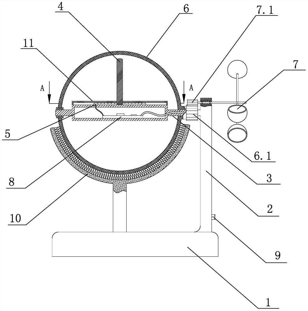
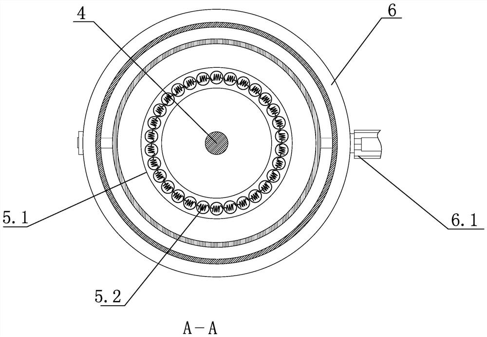
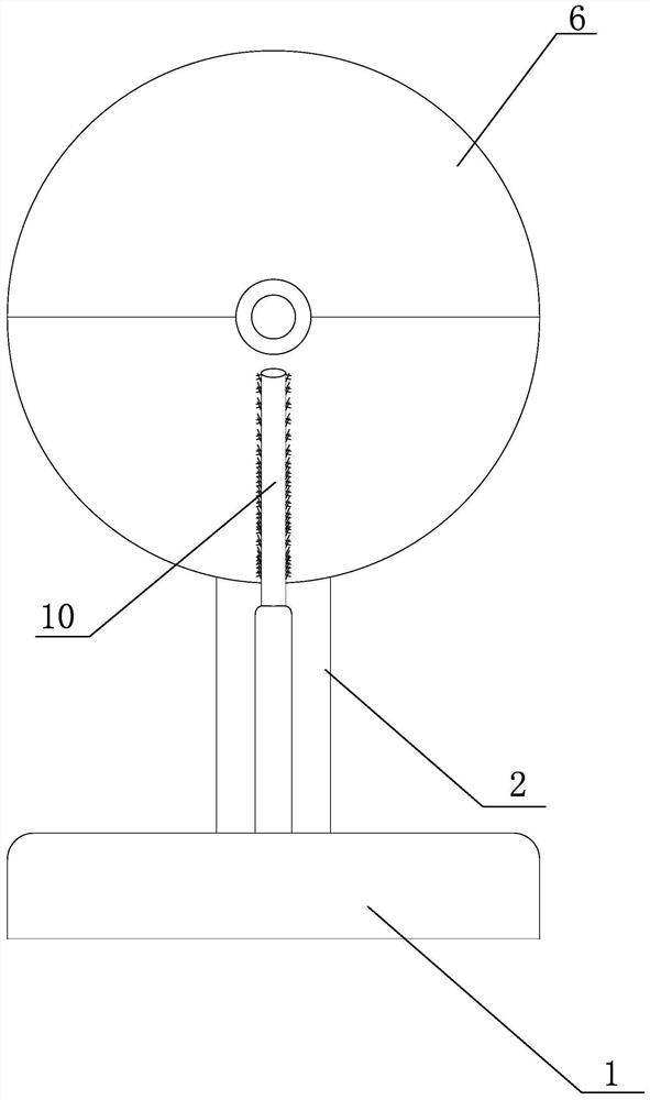
[0025] Such as Figure 1-4 Shown, a kind of sun azimuth measurement sensor comprises base 1, the pillar 2 that is vertically fixed on the base 1 and the horizontal fixed axis 3 that is located on the pillar 2;

[0026] The horizontal fixed shaft 3 is provided with a circular base, and the upper surface of the circular base is provided with a projection needle 4; the projection needle 4 is perpendicular to the upper surface of the circular base; the projection needle 4 Made of opaque material, its bottom end is fixed at the center of the upper surface of the circular base, that is, the projection needle 4 is coaxial with the circular base;

[0027] The upper surface of the circular base surrounds the projection needle 4 with an annular photoresistor array 5, the annular photoresistor array 5 is composed of N photoresistors 5.2 numbered 1 to N arranged in series on the annular substrate 5.1 Composition; the adjacent photoresistors 5.2 on the annular substrate 5.1 are closely ar...


PUM


Abstract

The invention discloses a solar azimuth measurement sensor, comprising a base (1), a support (2) vertically fixed on the base (1), and a horizontal fixed shaft (3) arranged on the support (2); the horizontal fixed shaft (3) is provided with a circular base, and a projection needle (4) is provided on the upper surface of the circular base; the projection needle (4) is perpendicular to the upper surface of the circular base; the projection needle (4) Made of opaque material, the bottom end of which is fixed at the center of the upper surface of the circular base; the invention can effectively resist interference and has high accuracy of orientation sensing.

Description

technical field [0001] The invention relates to the technical field of sensors, in particular to a sun azimuth measurement sensor. Background technique [0002] Existing solar azimuth measurement sensors generally directly detect the difference in the intensity of sunlight on both sides of the base surface to determine the azimuth, which will lead to confusion and unclear indications of the sensor under cloudy conditions, especially giving wrong azimuth feedback. Few of the schemes based on the sun shadow discrimination method have the situation that environmental pollutants interfere with the sensor due to unreasonable structure, such as fallen leaves or dust covering the shadows that cause interference and make the sensor unable to determine the true orientation. Contents of the invention [0003] The technical problem to be solved by the present invention is to overcome the above disadvantages of the prior art: to provide a sun azimuth measurement sensor with effective ...

Claims


Application Information

Patent Timeline
Patent Type & Authority Patents(China)
IPC IPC(8): G01C1/00G05D3/12
CPCG01C1/00G05D3/12
Inventor 顾少云
Owner 苏州市东挺河智能科技发展有限公司
Why Eureka
Try Eureka