
Eureka
For R&D, Eureka makes reading and utilizing patents & technical documents easy.
Eureka AIR
Designed for self-driven R&D workflows. Generate viable solutions, solve complex R&D challenges, empower your innovation with AI.

Eureka Materials
Designed for material experts only. Revolutionize your material R&D, from search, analyze, to developing new materials.

TechResearch
Generate reliable direction feasibility study reports for your R&D in just a few steps.

TechSeek
Discover and master advanced knowledge NOW. Basics, ideas, possibilities, all at once.

TechMind
As an expert in R&D Theories, TechMind can generates customized viable solutions instantly.

TechRisk
Analyze your overall solution with one click, know your potential R&D risks in advance.

TechMonitor
Get weekly tech updates, stay abreast of the latest tech innovations and key insights.
Two-dimensional code learning equipment for test paper
A two-dimensional code and equipment technology, applied in the field of education and teaching, can solve problems such as powerlessness, ordinary printers do not have, and test question answering is not very flexible, etc., to achieve the effect of good understanding
- Summary
- Abstract
- Description
- Claims
- Application Information
AI Technical Summary
Problems solved by technology
Method used
Image

Examples
Embodiment 1
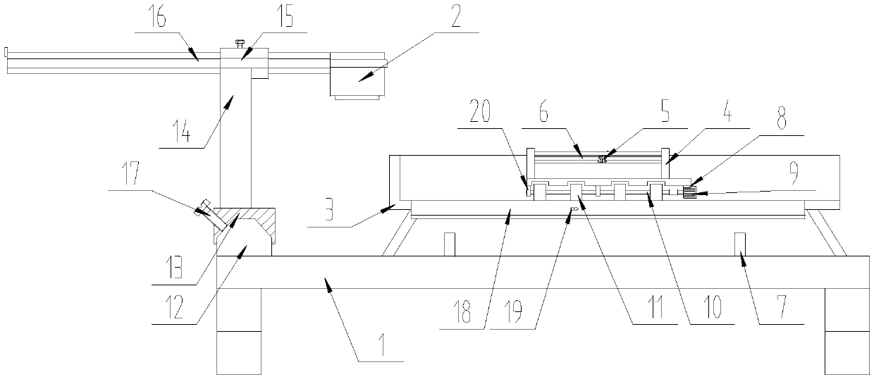
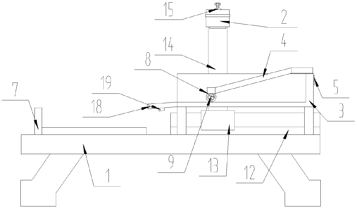
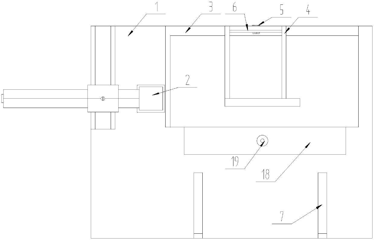
[0023] refer to Figure 1 ~ Figure 4 , a two-dimensional code learning device for test papers, at least including a base frame 1 and a laser engraving head 2, an adjustment device is fixed on the upper wall of the base frame 1, and the adjustment device is detachably installed with the generation head 2. On the upper wall of the base frame 1 and below the generating head 2, a bearing frame 3 is fixed. The bearing frame 3 is a groove structure, and one side of the bearing frame 3 is movably connected with a pressing frame, and the pressing frame includes a pressing rod 4, a special-shaped Spring 5, pin 6; one end of the pressing rod 4 is movably connected with the bearing frame 3 through the pin 6, the special-shaped spring 5 is set on the outer circumferential surface of the pin 6, and the acting ends of the two ends of the special-shaped spring 5 respectively act on Between the bearing frame 3 and the pressing rod 4, the other side of the bearing frame 3 and the upper wall of...
Embodiment 2
[0026] refer to Figure 1 ~ Figure 3 Compared with Embodiment 1, the difference of this embodiment is that the adjustment device includes a slide rail 12, a slide block 13, a support frame 14, a guide tube 15, and a guide tube 16, and the slide rail 12 is parallel to the bearing frame 3 is fixed on the upper wall of the base frame 1, the slider 13 is fitted on the slideway of the slide rail 12, one end of the support frame 14 is fixed on the slider 13 perpendicular to the slide rail 12, and the guide tube 15 supports the frame horizontally 14 is fixed on the other end of the support frame 14, and the angle between the guide tube 15 and the support frame is a right angle, the guide tube 16 is movably inserted in the guide tube 15, and the generating head 2 is detachably connected to one end of the guide tube 16 , and located above the carrier 3.
[0027] In actual use: the slider 13 moves on the slide rail 12, and at the same time drives the support frame 14 to move, and the m...
Embodiment 3
[0029] refer to Figure 1 ~ Figure 3 Compared with Embodiment 1, the difference of this embodiment is that: the slide block 13 and the guide pipe 15 are provided with threaded holes, and screw rods 17 are provided in the threaded holes.
[0030] During actual use: after the slider 13 moves, the screw rod 17 on the rotating slider 13 can temporarily fix the slider to prevent movement. After the guide tube 16 moves, rotate the screw rod 17 on the guide tube 15 to fix the guide tube 16 Temporary fastening to prevent movement.
PUM
 Abstract
Description
Claims
Application Information
 - R&D Engineer
- R&D Manager
- IP Professional
- Industry Leading Data Capabilities
- Powerful AI technology
- Patent DNA Extraction
Browse by: Latest US Patents, China's latest patents, Technical Efficacy Thesaurus, Application Domain, Technology Topic, Popular Technical Reports.
© 2024 PatSnap. All rights reserved.Legal|Privacy policy|Modern Slavery Act Transparency Statement|Sitemap|About US| Contact US: help@patsnap.com