Ultra-low frequency vibration isolator and designing method thereof

A vibration isolator and ultra-low frequency technology, which is applied in the direction of shock absorbers, mechanical equipment, springs/shock absorbers, etc., can solve the problems of high process cost of radial magnetized permanent magnets, high processing costs of ring permanent magnets, and high assembly costs , to achieve the effects of reducing assembly cost, reducing the lower limit cut-off frequency of vibration isolation, and reducing processing accuracy

Active Publication Date: 2020-05-01
CHANGSHA UNIVERSITY OF SCIENCE AND TECHNOLOGY
View PDF10 Cites 3 Cited by
  • Summary
  • Abstract
  • Description
  • Claims
  • Application Information

AI Technical Summary

Problems solved by technology

An invention patent titled "A Parallel Shock Absorber with Positive and Negative Stiffness" (application number CN201310142491.9) proposes a shock absorber based on a parallel connection of a positive stiffness air spring and a negative stiffness magnetic spring. The positive stiffness air spring Arranged in parallel with the negative stiffness magnetic spring, the negative stiffness magnetic spring is installed in the air spring chamber, the problem is that the negative stiffness mechanism is composed of multiple radially magnetized tile-shaped permanent magnets, and the process cost of radially magnetized permanent magnets is high and difficult Large, while the negative stiffness magnetic spring is composed of a large number of permanent magnets, so the processing is complicated and the assembly cost is extremely high
[0006] An invention patent named an ultra-low frequency vibration isolator and its design method (application number: 2019105719451), using an axially magnetized annular permanent magnet as a negative stiffness element, and considering the impact of the vibration source amplitude on the performance of the vibration isolation system during the design process However, the processing cost of the axially magnetized annular permanent magnet is high, and at the same time, it can require two permanent magnets to be concentric and require high precision during assembly, which has the disadvantages of high assembly cost and difficulty

Method used


Image

  • Ultra-low frequency vibration isolator and designing method thereof
  • Ultra-low frequency vibration isolator and designing method thereof
  • Ultra-low frequency vibration isolator and designing method thereof

Examples


Embodiment Construction

[0037] The following will clearly and completely describe the technical solutions in the embodiments of the present invention in conjunction with the accompanying drawings of the present invention. Obviously, the described embodiments are only some, not all, embodiments of the present invention. Based on the embodiments of the present invention, all other embodiments obtained by persons of ordinary skill in the art without making creative efforts belong to the protection scope of the present invention.

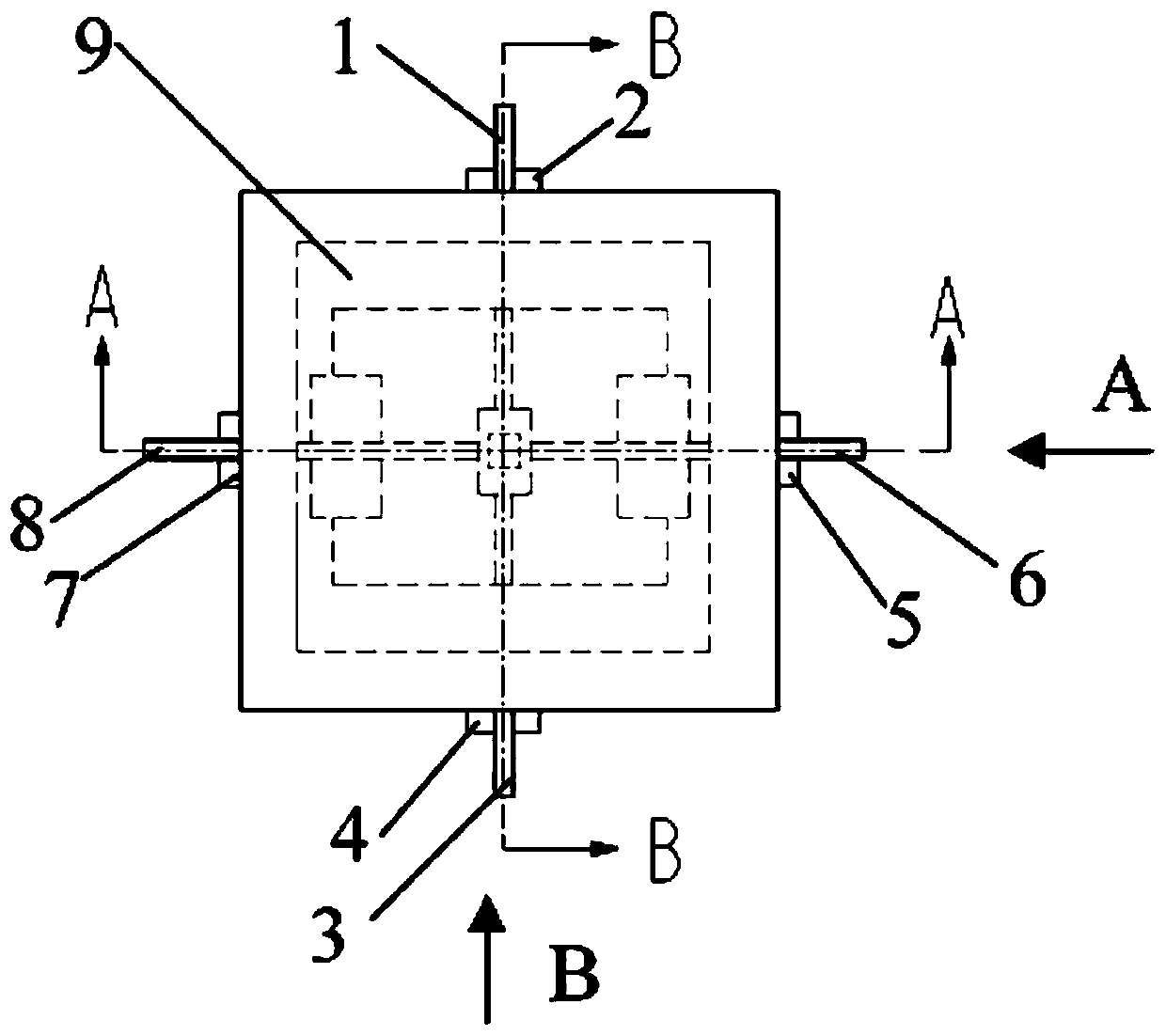
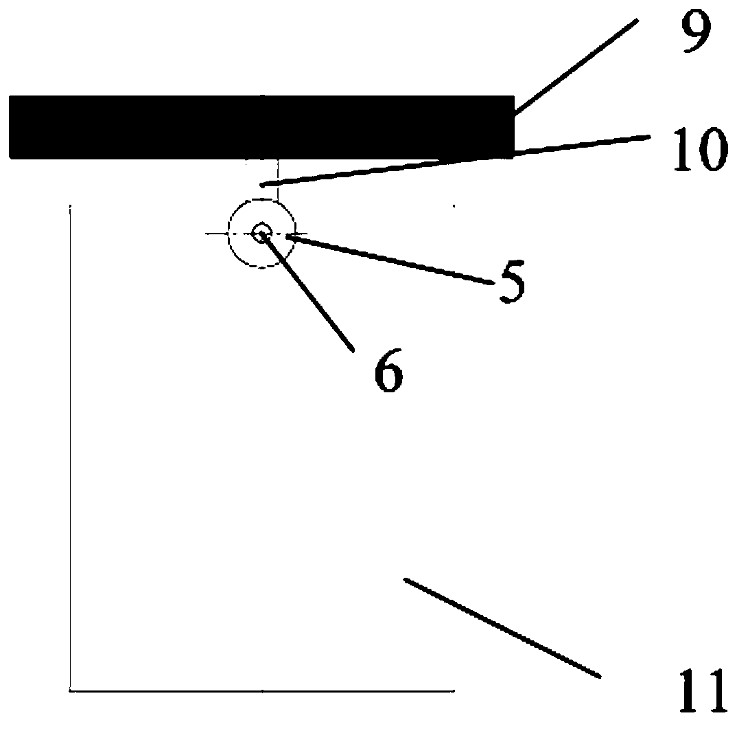
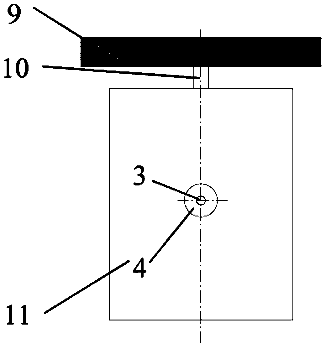
[0038] Such as Figure 1 to Figure 4 As shown, an ultra-low frequency vibration isolator disclosed in the present invention includes a vibration isolation bearing plate 9, a rectangular housing 11, an upper rigid rod 10, a lower rigid rod 14, an upper adjustment mechanism, a lower adjustment mechanism, and has a negative stiffness characteristic The negative stiffness element and the linear elastic element 26 with positive stiffness characteristics, in this embodiment, the lin...


PUM


Abstract

The invention discloses an ultra-low frequency vibration isolator which comprises a vibration isolation bearing platen, a rectangular shell, an upper rigid rod, a lower rigid rod, an upper adjusting mechanism, a lower adjusting mechanism, a negative rigidity element with the negative rigidity characteristic and a linear elastic element with the positive rigidity characteristic. The invention further discloses a designing method of the ultra-low frequency vibration isolator. The assembling structure is simple, the requirement for high-precision of concentric installation is avoided, the vibration isolator can keep the linear low-rigidity characteristic near the working point of the vibration isolator, and therefore the amplitude restriction for the performance of the vibration isolator canbe eliminated. Accordingly, the excellent low-frequency vibration isolation performance is achieved.

Description

technical field [0001] The present invention relates to the field of ultra-low frequency vibration reduction and isolation, in particular to an ultra-low frequency vibration isolator and its design method [0002] technical background [0003] With the continuous development of a series of ultra-precision processing and measurement technologies represented by ultra-precision grinding, semiconductor processing, micro-nano manufacturing, and surface topography measurement, the processing and measurement accuracy is getting closer and closer to the physical limit. Therefore, the tiny environment Vibration may cause its processing or detection failure. In order to ensure the accuracy of processing and measurement, this type of processing and measuring equipment puts forward extremely high requirements on environmental vibration. Generally speaking, environmental vibration is generally distributed in the low-frequency ultra-low frequency range, and is distributed in a certain fre...

Claims


Application Information

Patent Timeline
Patent Type & Authority Applications(China)
IPC IPC(8): F16F6/00F16F15/04
CPCF16F15/03F16F15/046F16F2222/06F16F2238/022
Inventor 周振华刘志强刘鑫周民瑞戴志辉
Owner CHANGSHA UNIVERSITY OF SCIENCE AND TECHNOLOGY
Why Eureka
Try Eureka