Mobile terminal positioning system and method
A mobile terminal and positioning system technology, applied in positioning, radio wave measurement systems, services based on specific environments, etc., can solve the problems of high indoor positioning deployment cost, high complexity, and susceptibility to interference.
Inactive Publication Date: 2020-05-19
SUNWAVE COMM
4 Cites 2 Cited by
AI-Extracted Technical Summary
Problems solved by technology
[0013] Based on this, it is necessary to provide a mobile terminal positioning system, method, computer equipment an...
Method used
As shown in Figure 18, because the power declines more obviously with the distance, the relative positioning detection value accuracy is higher, and the SRS arrival time is due to the electromagnetic wave transmission speed in the air is faster, and the indoor positioning distance is closer, using the electromagnetic wave transmission time to detect The distance accuracy is not high enough, so the terminal location is mainly based on the first terminal position obtained by power detection. At the same time, the received terminal signal power is used as the positioning basis, and the SRS arrival time is used as supplementary data for positioning correction to avoid errors caused by uneven power fading. Compared with using single RSSI positioning technology, single RSSI positioning is based on signal strength positioning, and is susceptible to the impact of moving obstacles (such as human bodies) on RSSI; the method of this embodiment provides additional time difference positioning information that is not affected by occlusion, improving It improves the indoor positioning accuracy and reduces the interference of moving objects to single RSSI positioning.
[0079] Existing indoor positioning technologies include WIFI and Bluetooth positioning, etc. Different from methods using base station technology for positioning, wireless positioning technologies require additional wireless positioning devices and servers, which require additional overhead. The base station positioning technology can locate as long as there is a base station signal coverage, without the overhead of additional equipment. However, the existing base station positioning technology is not suitable for indoor posit...
Abstract
The invention relates to a mobile terminal positioning system and method, and the system comprises a far-end unit and a central unit, the far-end unit is used for deploying a physical layer, receivinga terminal signal, and obtaining related parameters of the terminal signal through the physical layer; the central unit is used for deploying an MAC layer, receiving related parameters sent by the far-end unit, and obtaining the position of a terminal according to the related parameters. By changing a software protocol stack, a positioning function is realized on the basis of mobile signal coverage, an additional positioning system does not need to be deployed, and the problems of high deployment cost and high deployment complexity of the positioning system are solved; the positioning function can be realized as long as the position of the base station signal is covered, the system positioning signal coverage is continuous and stable, and the problems of small positioning system coveragerange and discontinuous positioning signal coverage are solved; coverage signals of the base station system are used for positioning, extra positioning signal interference is avoided, and the problemthat a positioning system is easily interfered by other wireless signals is solved.
Application Domain
Power managementParticular environment based services +1
Technology Topic
Embedded systemReal-time computing +8
Image
Examples
- Experimental program(1)
Example Embodiment
[0058] In order to make the objectives, technical solutions and advantages of the present invention clearer, the following further describes the present invention in detail with reference to the accompanying drawings and embodiments. It should be understood that the specific embodiments described herein are only used to explain the present invention, but not to limit the present invention.
[0059] It should be noted that the term "first\second\third" involved in the embodiment of the present invention is only to distinguish similar objects, and does not represent a specific order for the objects. Understandably, "first\second\ "Third" can be interchanged in specific order or precedence when permitted. It should be understood that the objects distinguished by "first\second\third" can be interchanged under appropriate circumstances, so that the embodiments of the present invention described herein can be implemented in an order other than those illustrated or described herein.
[0060] The terms "including" and "having" and any variations thereof in the embodiments of the present invention are intended to cover non-exclusive inclusions. For example, a process, method, system, product, or device that includes a series of steps or (module) units is not limited to the listed steps or units, but optionally also includes unlisted steps or units, or optional The ground also includes other steps or units inherent to these processes, methods, products or equipment.
[0061] Reference to "embodiments" herein means that a specific feature, structure, or characteristic described in conjunction with the embodiments may be included in at least one embodiment of the present application. The appearance of the phrase in various places in the specification does not necessarily refer to the same embodiment, nor is it an independent or alternative embodiment mutually exclusive with other embodiments. Those skilled in the art clearly and implicitly understand that the embodiments described herein can be combined with other embodiments.
[0062] The "plurality" mentioned herein means two or more. "And/or" describes the association relationship of the associated object, indicating that there can be three types of relationships, for example, A and/or B, which can mean: A alone exists, A and B exist at the same time, and B exists alone. The character "/" generally indicates that the associated objects are in an "or" relationship.
[0063] The Distributed Relay System (DRS) includes a central unit, an expansion unit and a remote unit. The whole system is an independent distributed system, which realizes indoor signal coverage of the mobile communication network. The central unit is responsible for the data transmission of the mobile communication protocol stack, the expansion unit is responsible for data forwarding, the remote unit is responsible for radio signal transmission, and the remote units are distributed in various indoor areas for mobile communication signal coverage.
[0064] The terminals described herein can be, but are not limited to, smart phones, tablet computers, notebook computers, wearable devices, etc.
[0065] In one embodiment, a mobile terminal positioning system is configured based on the DRS system, such as Figure 7 , Including a central unit and multiple expansion units, multiple expansion units and multiple remote units cascaded. The entire system is a base station system that only covers the signal of one cell. Each remote unit and antenna can be distributed to different locations, and each remote unit and antenna transmits the same cell signal.
[0066] The meaning of a cell in this article refers to the signal range that the DRS system including a central unit can cover. It can be a residential area in the usual sense, a floor of an indoor shopping mall, a part of the audience area of a large stadium, and so on.
[0067] The mobile terminal positioning system includes three types of modules: central unit, expansion unit and remote unit. Including a central unit, the central unit hangs several expansion units, and each expansion unit hangs several remote units.
[0068] The central unit, extension unit, and remote unit described in this article should not only be understood as the deployment of a three-level structure. For example, the extension unit can be omitted when the layout range does not require an extension unit. For example, when the layout range requires an extension unit, the extension unit Units can include first-level expansion units, second-level expansion units, and so on.
[0069] The central unit can be any device that can realize the data transmission function. For example, the central unit can be a base station or a baseband processing unit (Building Base Band Unit, BBU).
[0070] The expansion unit is any device that can realize the data forwarding function, and it is a device used by the DRS system to expand multiple remote sites after being remote.
[0071] The so-called central unit, extension unit and remote unit are a relative description. The spatial distance between the central unit, extension unit and remote unit can be large or small; for example, the central unit can be extended to the extension unit and The remote unit, central unit, expansion unit and remote unit may also be integrated into one device.
[0072] The baseband signals are transmitted to each other between the central unit, the expansion unit and the remote unit. The remote unit can be regarded as a part of the base station, similar to the antenna unit of a traditional base station, except that the radio frequency signal is transmitted to the antenna unit, and the baseband signal is transmitted to the remote unit here.
[0073] This system expands the positioning function and splits and changes the protocol stack function on the basis of the distributed system architecture. Such as Figure 8 As shown, the functional segmentation diagram of the software protocol stack of the mobile terminal positioning system, the L2 (MAC layer) and L3 (RRC, RRM, etc.) of the protocol stack are implemented in the central unit, and the L1 (physical layer) of the protocol stack is implemented in the remote unit; Deploy the physical layer to the remote unit to receive the terminal signal, and obtain the relevant parameters of the terminal signal through the physical layer. Each remote unit can independently detect the delay difference and signal strength of the signal sent by the mobile terminal. The central unit receives the relevant parameters (delay difference and signal strength) sent by the remote unit, and obtains the location of the terminal according to the relevant parameters. The physical layer L1 is deployed to the remote unit for independent deployment, and the function of the physical layer itself is not changed; usually there is only one physical layer in the central unit, and in this embodiment, each remote unit has a physical layer, and the central unit is no longer The physical layer is required.
[0074] Specifically, the remote unit includes a DSP module for realizing all the functions of the physical layer L1.
[0075] In an embodiment, the mobile terminal positioning system further includes a positioning module, which is used to obtain the positioning of the terminal according to related parameters. The positioning module is an independent new function from the general DRS system protocol stack, and a new software function module needs to be added, and the MAC layer will interact the collected information with the positioning module.
[0076] Further, the mobile terminal positioning system also includes a power control module, and the power control module needs to control the terminal to regulate power through the MAC.
[0077] The MAC layer protocol of the L2 protocol adds a management function to the terminal information detected on the remote unit side. The MAC layer of L2 adds and stores terminal information detected by each remote unit, Picture 9 The MAC layer shown in at least includes RU1 info, RU2info, and RU3 info, corresponding to the terminal information detected by the remote units RU1, RU2, and RU3, respectively. Each remote unit has a physical layer, and the information detected by each physical layer is different. The MAC layer needs to summarize the information of each physical layer, and the data of each remote unit is stored independently for positioning Module and power control module provide data. If there are multiple MAC layers, each MAC needs to save data.
[0078] Specifically, the L3 and above parts will not be modified to ensure that the basic functions of the DRS system will not be affected.
[0079] Existing indoor positioning technologies include WIFI and Bluetooth positioning, etc., which are different from methods that use base station technology for positioning. The wireless positioning technology requires additional wireless positioning equipment and servers, and requires additional overhead. The base station positioning technology can be positioned as long as there is a base station signal coverage, without the overhead of additional equipment. However, the existing base station positioning technology is not suitable for indoor positioning. The terminal positioning system in the embodiment of the present invention implements positioning detection calculations inside the base station without additional network support, no additional deployment of indoor positioning systems, and mobile signals in the DRS indoor Adding functions on the basis of coverage can reduce deployment cost and difficulty, while reducing detection delay. It uses the coverage signal of the base station system itself for positioning, avoiding additional positioning signal interference, and improving the continuity and coverage of signal coverage. There is no need for additional network support for the positioning function, which reduces signaling transmission overhead and detection delay, and can reduce deployment difficulty. The system positioning signal coverage is continuous and stable, and the positioning function can be realized as long as there is a position covering the base station signal.
[0080] Such as Picture 10 As shown, the signaling transmission and reception schematic diagram of the mobile terminal positioning system, the signaling used for terminal positioning mainly includes three: the uplink transmit power control command (TPC) sent by the central unit to the terminal, and the physical uplink shared channel of the terminal (Physical Uplink Shared Channel, PUSCH), the uplink sounding reference signal (Sounding Reference Signal, SRS) of the terminal.
[0081] 1) Uplink transmit power control command (TPC), used to adjust the transmit power of the terminal, so that at least one remote end can normally receive the terminal's signal.
[0082] 2) The remote unit detects the signal strength (RSSI) of the terminal's uplink shared channel (PUSCH) signal to the remote unit, and the arrival time T of the terminal's uplink sounding reference signal (SRS) to the remote unit, and reports it to the central unit.
[0083] The positioning system of this embodiment is implemented on the basis of the DRS system, such as Picture 11 , Only need to establish a cell to be able to locate, do not need multiple cell coordination. The positioning system has a built-in physical layer protocol on each remote unit (Remote Unit, RU), so that each RU can detect the power of the signal from the user equipment/terminal (User Equipment, UE) and the arrival time of the SRS signal. Compared with the OTDOA positioning method, OTDOA requires coordinated positioning of multiple base stations, there is overhead in communication between base stations, and the cost of deploying multiple base stations at the same time is high; in the terminal positioning system of the embodiment of the present invention, a single DRS system can realize the positioning function , Which can reduce the difficulty and cost of deployment and increase the positioning speed.
[0084] The remote unit in the terminal positioning system can arbitrarily adjust the position, quantity, and coverage (transmission power) according to the trade-off between coverage area requirements and positioning requirements; in the initial deployment of the remote unit, according to the requirements of the positioning function and coverage For signal range requirements, the layout and number of remote units should be adjusted to a certain extent to facilitate the perfect integration of positioning function and signal coverage. Deploy multiple remote units at different indoor locations for signal coverage and record location information.
[0085] In one embodiment, multiple remote units receive signals from the same terminal. Each remote unit independently detects the RSSI of the terminal to the remote unit and the arrival time T of the SRS of the terminal to the remote unit, and reports to the central unit respectively.
[0086] For example, remote units A, B, and C receive signals from the same terminal, and remote unit A independently detects the signal strength RSSI of the signal from the terminal to remote unit A A , The remote unit A independently detects the arrival time T of the terminal SRS to the remote unit A A , And then report to the central unit; remote units B and C also report the independently detected information to the central unit.
[0087] The remote unit detects the transmitted signal strength RSSI and sounding reference signal SRS arrival time of each terminal in real time, and reports to the central unit.
[0088] The central unit summarizes the information reported by the remote unit and decomposes the signal strength RSSI and SRS arrival time corresponding to the same frame signal sent by the terminal.
[0089] The central unit calculates the location of the terminal according to the signal strength RSSI and SRS arrival time of the same frame signal sent by the terminal.
[0090] The central unit calculates the terminal position according to the signal strength RSSI, the steps include:
[0091] Obtain the signal strength RSSI of the signal from the terminal to the remote unit, and calculate the distance d from the mobile terminal to the remote unit according to the corresponding relationship between signal strength and distance, such as Picture 12;
[0092] According to the radio attenuation model, the corresponding relationship between signal strength and distance is as follows:
[0093] d=10^((ABS(RSSI)-A)/(10*n))
[0094] Among them, d is the distance from the mobile terminal to the remote unit, ABS represents the absolute value, and RSSI is the signal strength; A is the absolute value of the RSSI value when the detection device is 1 m away; n is the environmental attenuation factor.
[0095] Get the distance from the same terminal to different remote units as d 1 , D 2 , D 3..., the positions of the remote units A, B, C... are known, and the position of the mobile terminal can be obtained according to the positioning algorithm.
[0096] There are many options for the positioning algorithm. In one embodiment, such as Figure 13 , As shown in the figure, A, B, and C represent three remote units, the three arrows point to the location of the terminal, d1, d2, and d3 are the calculated distances from the terminal to the three remote units; choose three Point positioning method calculates the position of the mobile terminal. In the three-point positioning method, first there are three dots, and the radii of the three circles are known. Finally, the intersection of the three circles is obtained to achieve the positioning effect; the purpose is to find the intersection of the three circles, which can be quickly obtained by using the Pythagorean theorem Get the coordinates of the intersection point.
[0097] The central unit calculates the terminal position according to the arrival time of the SRS signal, and the steps include:
[0098] The terminal and the central unit (through the L2 protocol stack) pre-arranged to send the SRS signal at time t1, the remote unit detects the time t2 when the SRS signal arrives at the remote unit, and calculates the time delay difference Δt for the mobile terminal to send the signal to the remote unit. t2-t1, calculate the distance D from the mobile terminal to the remote unit according to the delay difference Δt, such as Figure 14 , The calculation formula of distance D is;
[0099] D=ν×Δt
[0100] Among them, the transmission speed ν is the propagation speed of electromagnetic waves in the air, and the distance D is proportional to the time delay difference Δt. The longer the time, the farther the distance.
[0101] In one embodiment, the terminal and the remote unit have agreed in advance to send the SRS signal at time t1, and the appointment process is in accordance with the process of agreeing to send the SRS signal between the remote unit and the terminal defined by 3GPP. By detecting the time position of the periodic or aperiodic SRS subframe pre-set by the remote unit and the mobile phone, according to the subframe period and offset when sending the SRS subframe and the time position of the current received SRS subframe. Determine the time required for the SRS subframe signal to be transmitted from the terminal to the remote unit, thereby calculating the distance.
[0102] Get the distance from the same terminal to different remote units as D 1 , D 2 , D 3..., the positions of the remote units A, B, C... are known, and the position of the mobile terminal can be obtained according to the positioning algorithm. Here, the positioning algorithm can refer to the steps in which the central unit calculates the terminal position according to the signal strength RSSI.
[0103] The selection of the positioning algorithm is not limited to the method described in the foregoing embodiment, and any positioning algorithm that can obtain the positioning result can be used.
[0104] There is no limit to the number of remote units involved in positioning. If the number of remote units is large, certain criteria can be used for screening; if the number of remote units involved in positioning is small, the transmit power of the terminal can be adjusted through TPC commands. Such as Figure 15 , So that the area covered by the terminal can maintain a certain number of remote units that can detect the terminal's uplink signal.
[0105] In one embodiment, such as Figure 16 When more precise positioning is required, the central unit sends a TPC command to increase the terminal's transmit power, so that more remote ends can receive the terminal's uplink signal, and the calculated position is more accurate. The central unit judges whether it is necessary to send TPC commands to adjust the terminal's transmit power according to the RSSI detected by each remote unit; after the central unit confirms that at least N remote units can stably receive terminal signals, such as those received by N remote units If the terminal signal RSSI is higher than the set threshold, stop adjusting the terminal transmit power. Specifically, N may be an integer equal to or greater than 3.
[0106] In one embodiment, in the normal power control algorithm, that is, at least three remote units are arranged. If less than three remote units detect the same mobile phone terminal signal, the mobile phone transmission power needs to be adjusted so that three One or more remote units can detect the signal of the same mobile phone terminal; if three or more remote units can detect the same mobile phone signal, but the mobile phone signal is weak and the positioning accuracy is affected, then it is necessary Increase the transmission power of mobile phones to improve positioning accuracy.
[0107] In an embodiment, the central unit can obtain the first terminal position according to the signal strength RSSI, and the central unit can obtain the second terminal position according to the arrival time of the SRS signal.
[0108] Specific, such as Figure 17 The central unit mainly performs terminal positioning detection based on the first terminal position. When a remote unit receives poor signal quality, it supplements the second terminal position as a correction to improve the accuracy and precision of terminal positioning. When the signal is good, the first terminal position detected by the signal power is relatively close to the second terminal position detected by the SRS arrival time, and no correction is needed. Combining RSSI distance positioning and SRS arrival time difference positioning methods complement each other and can improve detection accuracy and precision.
[0109] In one embodiment, the first terminal position is compared with the second terminal position. If the two errors are within the allowable range, such as within 1%, the result of the first terminal position shall prevail, otherwise the result of the second terminal position shall prevail. Prevail.
[0110] Such as Figure 18 , Because the power fading with distance is more obvious, the relative positioning detection value accuracy is higher, and the SRS arrival time is due to the faster electromagnetic wave transmission speed in the air, and the indoor positioning distance is relatively short, the distance accuracy detected by the electromagnetic wave transmission time is not high enough. Therefore, the first terminal position obtained by power detection is mainly used for terminal positioning. At the same time, the received terminal signal power is used as the positioning basis, and the SRS arrival time is used as supplementary data for positioning correction to avoid errors caused by uneven power fading. Compared with the use of single RSSI positioning technology, single RSSI positioning is based on signal strength and is susceptible to the influence of moving obstructions (such as the human body) on RSSI; the method of this embodiment additionally provides time difference positioning information that is not affected by occlusion, which improves The indoor positioning accuracy is improved, and the interference of moving objects to single RSSI positioning is reduced.
[0111] In the usual DRS system, the physical layer is on the central unit, and the baseband signal from the physical layer is transmitted to the remote unit. In this embodiment, the L1 (physical layer) is sunk to the remote unit. The physical layer can analyze the received terminal signal strength and the arrival time of the SRS subframe, and each remote unit can independently detect the remote unit The distance from the terminal can realize the detection and positioning of the terminal position.
[0112] If the physical layer is not deployed to the remote unit, each remote unit needs 1.2288G of baseband data. If the physical layer is deployed to the remote unit, only the signaling between the physical layer and L2 needs to be transmitted to the remote unit. The data volume can be up to 100M~200M, and the data volume is reduced to the order of 10 times. As a result, the data transmission rate requirements of the central unit and the remote unit are greatly reduced, the link transmission pressure is reduced, the stability of the system is improved, and the difficulty of implementation is reduced.
[0113] The various modules in the aforementioned mobile terminal positioning system can be implemented in whole or in part by software, hardware and a combination thereof. The foregoing modules may be embedded in the form of hardware or independent of the processor in the computer device, or may be stored in the memory of the computer device in the form of software, so that the processor can call and execute the operations corresponding to the foregoing modules.
[0114] In one embodiment, a computer device is provided, including a memory and a processor, and a computer program is stored in the memory, and the processor implements the following steps when executing the computer program:
[0115] The terminal signal is detected in real time, the relevant parameters of the terminal signal are obtained through the physical layer, and the relevant parameters are reported to the central unit.
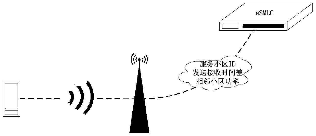
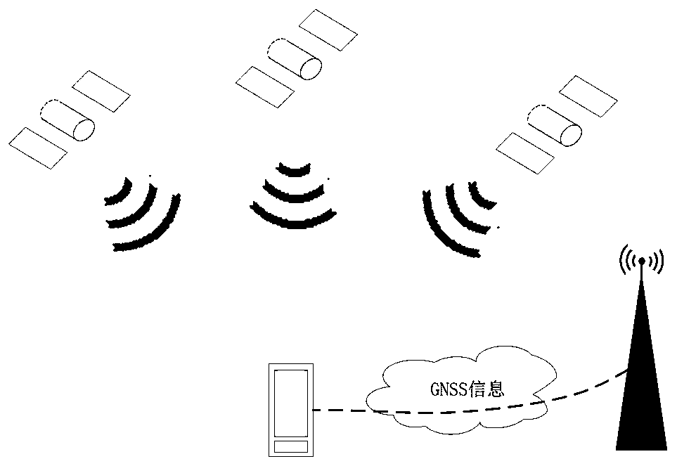
[0116] In one embodiment, the processor implements the following steps when executing the computer program:
[0117] Receiving relevant parameters sent by the remote unit, and obtaining the location of the terminal according to the relevant parameters.
[0118] In one embodiment, the processor implements the following steps when executing the computer program:
[0119] After receiving the relevant parameters sent by the remote unit, the relevant parameters corresponding to the same frame signal sent by the terminal are resolved, and the positioning of the terminal is obtained according to the relevant parameters corresponding to the same frame signal.
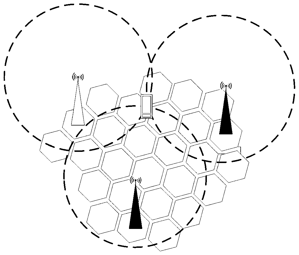
[0120] In one embodiment, the processor implements the following steps when executing the computer program:
[0121] Calculate the distance from the same terminal to at least three remote units according to the relevant parameters sent by at least three remote units with known locations, and calculate the position of the terminal according to the three-point positioning method.
[0122] In one embodiment, the processor implements the following steps when executing the computer program:
[0123] According to the signal strength of the uplink shared channel signal of the terminal detected by each remote unit to the remote unit, determine whether it is necessary to send an uplink transmission power control command to adjust the transmission power of the terminal; confirm that at least N remote units can stably receive the terminal signal After that, stop adjusting the terminal's transmit power.
[0124] In one embodiment, the processor implements the following steps when executing the computer program:
[0125] The first terminal position can be obtained according to the first relevant parameter, and the second terminal position can be obtained according to the second relevant parameter; the final terminal position can be obtained by combining the first terminal position and the second terminal position correction.
[0126] A person of ordinary skill in the art can understand that all or part of the processes in the above-mentioned embodiment methods can be implemented by instructing relevant hardware through a computer program. The computer program can be stored in a non-volatile computer readable storage. In the medium, when the computer program is executed, it may include the procedures of the above-mentioned method embodiments. Wherein, any reference to memory, storage, database or other media used in the embodiments provided in this application may include non-volatile and/or volatile memory. Non-volatile memory may include read only memory (ROM), programmable ROM (PROM), electrically programmable ROM (EPROM), electrically erasable programmable ROM (EEPROM), or flash memory. Volatile memory may include random access memory (RAM) or external cache memory. As an illustration and not a limitation, RAM is available in many forms, such as static RAM (SRAM), dynamic RAM (DRAM), synchronous DRAM (SDRAM), double data rate SDRAM (DDRSDRAM), enhanced SDRAM (ESDRAM), synchronous chain Channel (Synchlink) DRAM (SLDRAM), memory bus (Rambus) direct RAM (RDRAM), direct memory bus dynamic RAM (DRDRAM), and memory bus dynamic RAM (RDRAM), etc.
[0127] The technical features of the above-mentioned embodiments can be combined arbitrarily. In order to make the description concise, all possible combinations of the various technical features in the above-mentioned embodiments are not described. However, as long as there is no contradiction in the combination of these technical features, All should be considered as the scope of this specification.
[0128] The above-mentioned embodiments only express several embodiments of the present invention, and the descriptions are more specific and detailed, but they should not be understood as limiting the scope of the invention patent. It should be pointed out that for those of ordinary skill in the art, without departing from the concept of the present invention, several modifications and improvements can be made, and these all fall within the protection scope of the present invention. Therefore, the protection scope of the patent of the present invention should be subject to the appended claims.
PUM


Description & Claims & Application Information
We can also present the details of the Description, Claims and Application information to help users get a comprehensive understanding of the technical details of the patent, such as background art, summary of invention, brief description of drawings, description of embodiments, and other original content. On the other hand, users can also determine the specific scope of protection of the technology through the list of claims; as well as understand the changes in the life cycle of the technology with the presentation of the patent timeline. Login to view more.