An Imaging Method for Curved Synthetic Aperture Radar

A technology of synthetic aperture radar and imaging method, which is applied in the direction of reflection/re-radiation of radio waves, utilization of re-radiation, radio wave measurement system, etc. It can improve the focusing effect, expand the overlapping range, and reduce the loss of energy.

A technology of synthetic aperture radar and imaging method, which is applied in the direction of reflection/re-radiation of radio waves, utilization of re-radiation, radio wave measurement system, etc. It can improve the focusing effect, expand the overlapping range, and reduce the loss of energy.

CN111220979BActive Publication Date: 2022-05-13UNIV OF ELECTRONICS SCI & TECH OF CHINA

Image

  • An Imaging Method for Curved Synthetic Aperture Radar
  • An Imaging Method for Curved Synthetic Aperture Radar
  • An Imaging Method for Curved Synthetic Aperture Radar

Examples


Embodiment Construction

[0022] The present invention will be described in detail below in conjunction with the accompanying drawings and simulation examples to prove the practicability of the present invention.

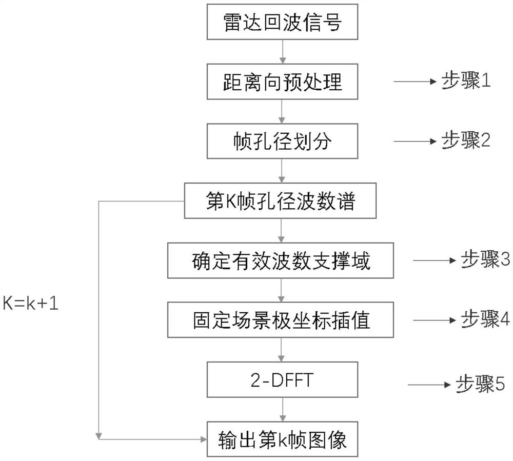
[0023] as attached figure 1 As shown, through the imaging method of a kind of curved synthetic aperture radar of the present invention, can input as the original echo of curved SAR, after imaging processing, obtain the two-dimensional image of curved SAR, concrete implementation steps are as follows:

[0024] Step 1: Perform distance preprocessing on the original echo: perform de-FM processing on the received signal to obtain the intermediate frequency signal s i (t,t), whose expression is:

[0025]

[0026] where R a (t) is the reference slope distance, △R(t)=R t (t)-R a (t), Tp is the signal pulse width, t is the fast time of the radar signal, t is the slow time of the radar signal, c is the speed of light, α is the frequency modulation slope of the radar signal, f c is the signal ...


PUM


Abstract

The invention belongs to the technical field of radar imaging, and in particular relates to an imaging method for curved synthetic aperture radar. The invention determines the specific position of the interpolation region by calculating the geometric center point of the wavenumber support domain, obtains an interpolation region covering a larger wavenumber support domain, and can make good use of the data information in the wavenumber support domain to improve the imaging quality. In addition, the present invention only involves simple arithmetic operations, and does not involve complex computing operations such as sliding windows. Therefore, the implementation of the present invention is also very simple.

Description

technical field [0001] The invention belongs to the technical field of radar imaging, and in particular relates to an imaging method for curved synthetic aperture radar. Background technique [0002] Synthetic aperture radar uses the correlation of radar echo signals to accumulate the Doppler shift of echo signals during radar motion, and synthesizes equivalent radar apertures in the direction of radar motion to achieve high-resolution imaging. It can realize all-day and all-weather regional monitoring and imaging. Curved SAR is a new mode of SAR, and its trajectory is a curve. Analyze the wavenumber domain distribution of the signal in the curved SAR mode. Since the direction of the radial wavenumber vector KR of the echo is consistent with the radial distance vector R of the radar relative to the target, when the radar trajectory is a curve, the wavenumber of the radar echo The domain also presents an irregular distribution (like a scatter-like distribution), and a scatt...

Claims


Application Information

Patent Timeline
13 May 2022
Publication
CN111220979B
IPC
G01S13/90
CPC
G01S13/9011; G01S13/9088
Inventors
李晋; 刘兴航