
Camera module, electronic equipment and control method of camera module

A technology for camera modules and electronic equipment, which is applied to parts of color TVs, parts of TV systems, TVs, etc. It can solve problems such as the inability to realize high-magnification zoom functions, and achieve good shooting effects

Active Publication Date: 2020-06-09
VIVO MOBILE COMM CO LTD
View PDF4 Cites 10 Cited by
  • Summary
  • Abstract
  • Description
  • Claims
  • Application Information

AI Technical Summary

Problems solved by technology

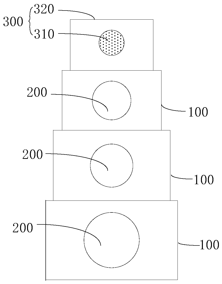
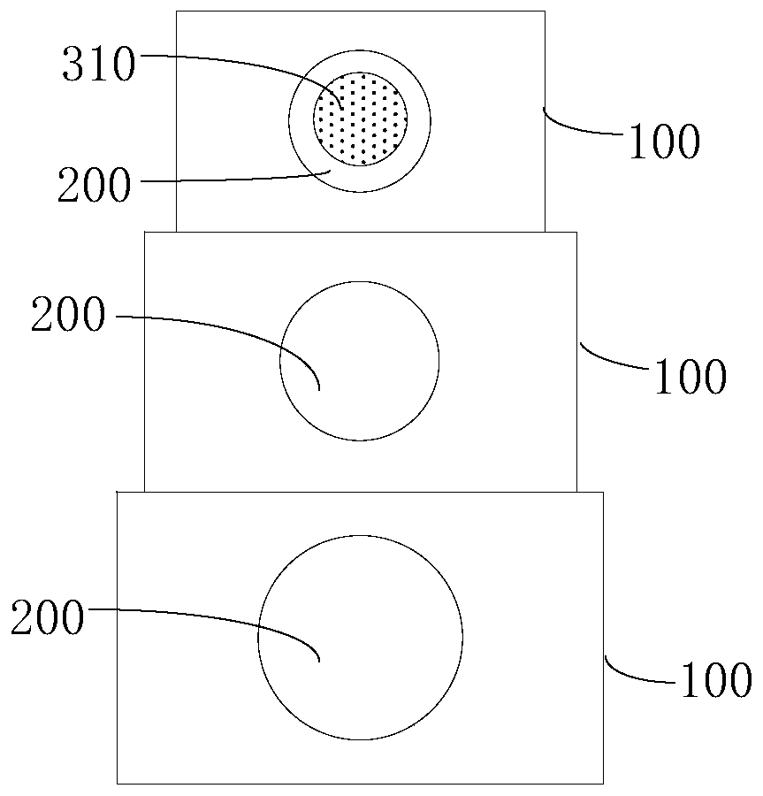
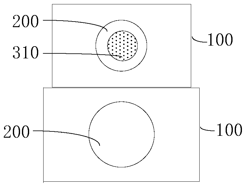
[0004] The invention discloses a camera module, electronic equipment and a control method of the camera module, which can solve the problem that the camera module of the current electronic equipment cannot realize the high-magnification zoom function

Method used


Image

  • Camera module, electronic equipment and control method of camera module
  • Camera module, electronic equipment and control method of camera module
  • Camera module, electronic equipment and control method of camera module

Examples


Embodiment Construction

[0022] In order to make the purpose, technical solution and advantages of the present invention clearer, the technical solution of the present invention will be clearly and completely described below in conjunction with specific embodiments of the present invention and corresponding drawings. Apparently, the described embodiments are only some of the embodiments of the present invention, but not all of them. Based on the embodiments of the present invention, all other embodiments obtained by persons of ordinary skill in the art without making creative efforts belong to the protection scope of the present invention.

[0023] The technical solutions disclosed by various embodiments of the present invention will be described in detail below in conjunction with the accompanying drawings.

[0024] Such as Figure 1 to Figure 6 As shown, the embodiment of the present invention discloses a camera module, and the disclosed camera module includes a first bracket 100 , a lens 200 and a...


PUM


Abstract

The invention discloses a camera module, electronic equipment and a control method of the camera module. The camera module comprises a first support, a lens arranged on the first support, and a cameraassembly comprising a camera and a second support. The camera is arranged on the second support, the second support is slidably connected with the first support in a sleeving mode, and the optical axis direction of the lens is parallel to the optical axis direction of the camera. At least one of the camera and the lens can move between a first position and a second position. When the camera or the lens is located at the first position, the projection of the camera in the optical axis direction and the projection of the lens in the optical axis direction are staggered. When the camera or the lens is located at the second position, the projection of the camera in the optical axis direction at least partially coincides with the projection of the lens in the optical axis direction. Accordingto the scheme, the problem that the camera module of the existing electronic equipment cannot realize a high-magnification zoom function is solved.

Description

technical field [0001] The invention relates to the technical field of communication equipment, in particular to a camera module, electronic equipment and a control method for the camera module. Background technique [0002] At present, with the advancement of technology and the continuous development of electronic equipment, electronic equipment has become an essential tool in work, entertainment, social and other scenarios, which makes users have higher and higher requirements for electronic equipment. Taking the camera module as an example, the shooting capability of electronic equipment has become an important criterion for measuring the performance of electronic equipment. With the continuous development of the camera module of electronic equipment, the number of cameras of the camera module is developing from a single camera to multiple cameras, so that the camera module can achieve a zoom effect, and thus the shooting effect of the camera module is better. [0003] H...

Claims


Application Information

Patent Timeline
Patent Type & Authority Applications(China)
IPC IPC(8): H04N5/225
CPCH04N23/54H04N23/50H04N23/57H04N23/55G03B30/00H04N23/51H04N23/61H04N23/62H04N23/69G02B15/02G03B17/04G03B5/00G03B2205/0046G02B7/021G02B7/08H04N23/667
Inventor 王志升
Owner VIVO MOBILE COMM CO LTD
Learn More