A method for controlling a moving head camera
A control method and camera technology, which is applied in the field of network communication, can solve problems such as calibration, head-shaking machine unable to perform position, and unable to effectively solve the problem of shaking head machine motor stall, idling position calibration, etc., to achieve the effect of solving physical interference
- Summary
- Abstract
- Description
- Claims
- Application Information
AI Technical Summary
Problems solved by technology
Method used
Image
Examples
Embodiment 1
[0037] Embodiment 1: A method for controlling a moving head camera.
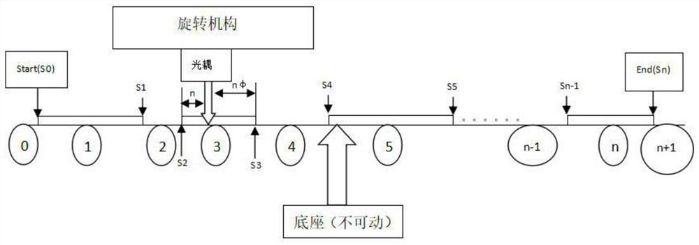
[0038] refer to figure 2 , image 3 , Figure 6 , Figure 7 and Figure 8 As shown, a control method for a moving head camera specifically includes the following steps:
[0039] S1. Install the optocoupler on the rotating mechanism, fix the baffle on the base, and the stepping motor drives the rotating mechanism to drive the optocoupler to move relative to the baffle.
[0040] S2. Divide the baffle into n sections. The length of each baffle is different, and the distance between each baffle is different. The optocoupler tube is installed across the baffle. When the optocoupler moves to the position with the baffle, The optocoupler is not conducting to the tube, and the state is set to 1, otherwise, the optocoupler is conducting, and the state is set to 0. When the rotating mechanism moves from the beginning to the end of the journey, the multi-stage baffle will change the conduction of the optocoupler ...
Embodiment 2
[0048] Embodiment 2: a method for controlling a moving head camera.
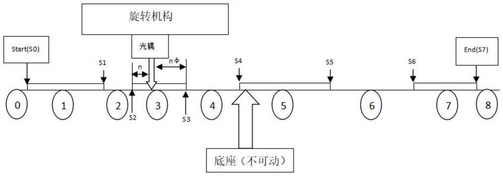
[0049] refer to Figure 4 , Figure 5 , Figure 6 , Figure 7 and Figure 8 As shown, a control method for a moving head camera specifically includes the following steps:
[0050] S1. Fix the optocoupler on the base, install the baffle on the rotating mechanism, and the stepping motor drives the rotating mechanism to drive the baffle to move relative to the optocoupler.
[0051] S2. Divide the baffle into n sections. The length of each baffle is different, and the distance between each baffle is different. The optocoupler tube is installed across the baffle. When the baffle moves to the position of the optocoupler, The coupling-to-tube is not conducting, set the state to 1, otherwise, the optocoupler is conducting, set the state to 0, when the rotating mechanism moves from the beginning to the end of the journey, the multi-segment baffle will change the conduction of the optocoupler to the tube several ...
PUM
 Abstract
Description
Claims
Application Information
 - R&D
- Intellectual Property
- Life Sciences
- Materials
- Tech Scout
- Unparalleled Data Quality
- Higher Quality Content
- 60% Fewer Hallucinations
Browse by: Latest US Patents, China's latest patents, Technical Efficacy Thesaurus, Application Domain, Technology Topic, Popular Technical Reports.
© 2025 PatSnap. All rights reserved.Legal|Privacy policy|Modern Slavery Act Transparency Statement|Sitemap|About US| Contact US: help@patsnap.com


