
Burr scraping device and method for precision machining

A technology of scraping device and precision machinery, which is applied in the field of precision machining, can solve the problems affecting the smoothness and precision quality of the workpiece surface, the problem of adapting the burr scraping device, and low adaptability, so as to improve safety and processing efficiency , Convenient, fast and precise position installation, fast and high-precision burr scraping effect

Inactive Publication Date: 2021-12-14
新昌县善力机械科技有限公司
View PDF0 Cites 0 Cited by
  • Summary
  • Abstract
  • Description
  • Claims
  • Application Information

AI Technical Summary

Problems solved by technology

[0002] When performing precision machining of metal parts, due to the extrusion of the cutting surface, burrs will be generated on the side of the cutting surface, which will affect the surface smoothness and precision quality of the workpiece
[0003] Most of the existing burr scraping devices are scraped by manual hand-held scrapers, which is very easy to cause scratches to fingers or scratches on the cutting surface, which has problems affecting accuracy and safety, and the efficiency is low. Due to the difference in the cutting surface of the workpiece in the device, the adaptability of the device is low. The surface processing burrs are generated on the side of the surface, and the drilling processing, the burrs are located at the upper and lower ports of the drilling hole.
[0004] To this end, a burr scraping device for precision machining and a scraping method are provided to solve the problem of adaptation and efficiency of the burr scraping device for precision machining

Method used


Image

  • Burr scraping device and method for precision machining
  • Burr scraping device and method for precision machining
  • Burr scraping device and method for precision machining

Examples


Embodiment 2

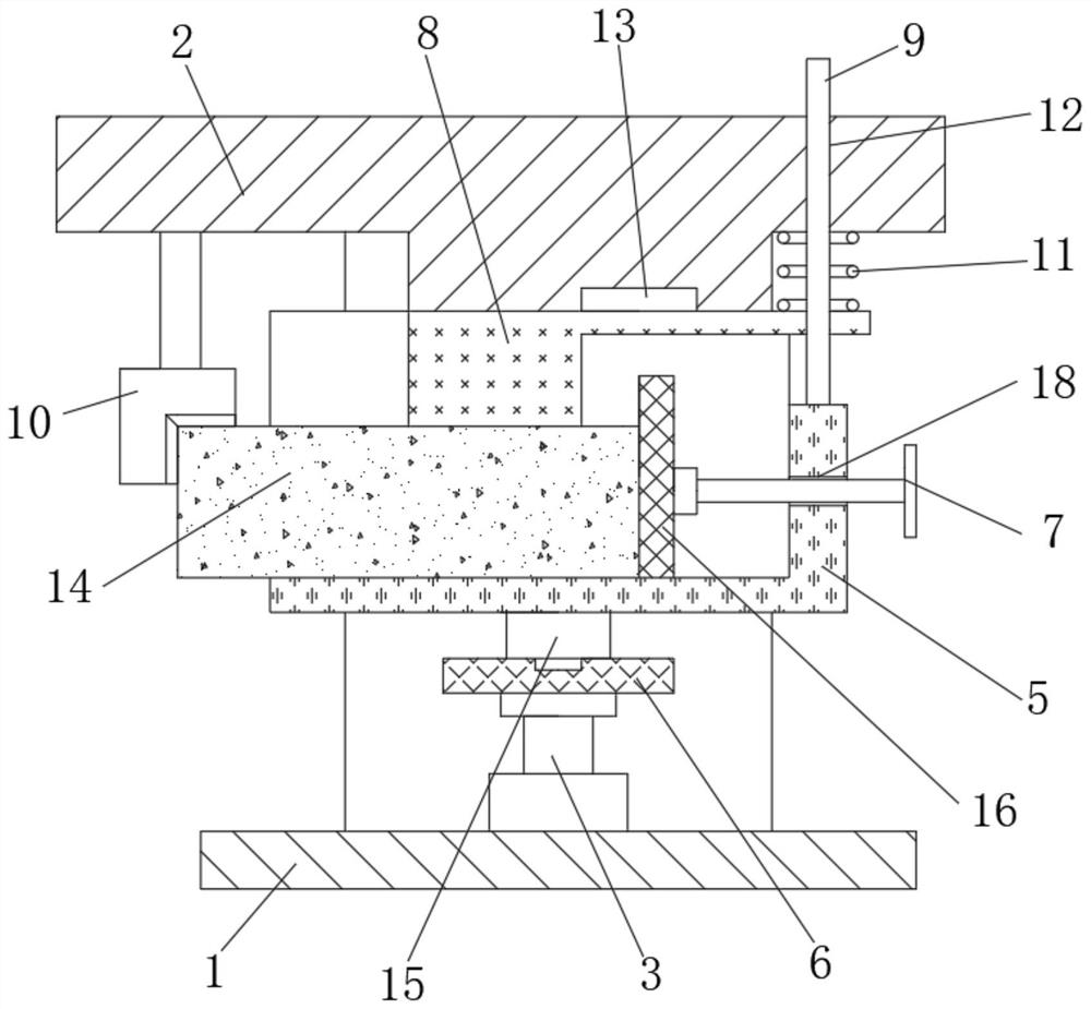
[0046] Embodiment 2: When the workpiece 14 is a drilling cutting surface, the burr is located at the drilling port, and the mounting block 5 is a ring frame, and the positioning of the workpiece 14 is realized by the limit extrusion of the cylindrical positioning block 16 and the fastening cover plate 8. Preliminary fixation, the mounting block 5 is squeezed by the positioning screw 7 to realize the horizontal sliding adjustment of the mounting block 5 on the guide rail 6, so that the burr port is located directly below the scraper 10;

[0047] The lifting column 3 rises to drive the scraping side to fit the scraper 10, and the fastening cover plate 8 presses the spring 11 to realize the fastening and fixing installation of the workpiece 14.

[0048] The driving device 4 adopts a rotating motor with a gear, and the motor drives the gear to mesh with the ring gear 19, so that the mounting block 5 rotates on the upper end of the slider 15, and realizes the circular rotation of th...


PUM


Abstract

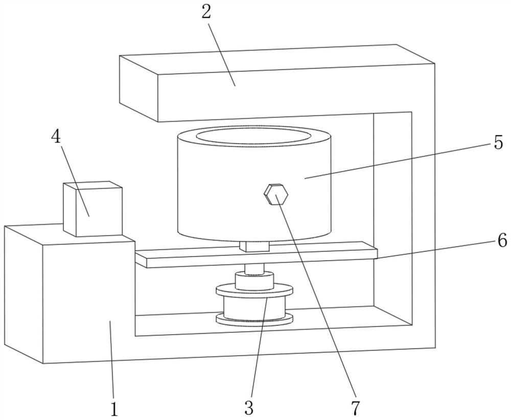
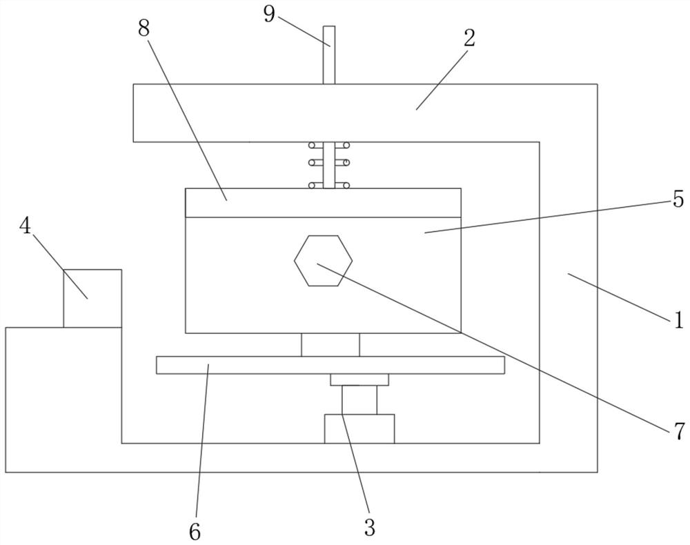
The invention relates to the technical field of precision machining, in particular to a burr scraping device and method for precision machining. The burr scraping device comprises a scraping device body, the scraping device body is composed of a base, an upper cross beam, a lifting column, a driving device, a mounting block, a guide rail, a positioning screw and a scraper, the base is parallel to the upper cross beam, the lower end of the lifting column is fixedly mounted in the middle of the upper end face of the base, and the guide rail is fixedly mounted on the lifting column. The burr scraping device and method for precision machining have the beneficial effects that through extrusion cooperation of a lifting device, the mounting block and a fastening plate, convenient, workpieces can be rapidly and accurately mounted, through cooperation of driving of the driving device, rapid burr scraping is achieved, through cooperation of a positioning device and the positioning screw, a machining position is accurately calibrated, through cooperation of position limiting of a guide stand column, cooperation of the scraper and a cutting position is achieved, therefore, for the workpieces in the same batch, rapid and high-precision burr scraping can be achieved, and convenient calibration and module mounting can be achieved for different workpieces.

Description

technical field [0001] The invention relates to the technical field of precision machining, in particular to a burr scraping device and a scraping method for precision machining. Background technique [0002] When performing precision machining of metal parts, due to the extrusion of the cutting surface, burrs will be generated on the side of the cutting surface, which will affect the surface smoothness and precision quality of the workpiece. [0003] Most of the existing burr scraping devices are scraped by manual hand-held scrapers, which is very easy to cause scratches to fingers or scratches on the cutting surface, which has problems affecting accuracy and safety, and the efficiency is low. Due to the difference in the cutting surface of the workpiece in the device, the adaptability of the device is low. The surface processing burrs are generated on the side of the surface, and the drilling processing, the burrs are located at the upper and lower ports of the drilling ho...

Claims


Application Information

Patent Timeline
IPC IPC(8): B23D79/04
CPCB23D79/04
Inventor 王倩儿
Owner 新昌县善力机械科技有限公司
Learn More