
Edge banding machine for toy production

A technology for edge banding machines and toys, applied in toys, home appliances, and other home appliances, can solve the problems of inaccurate positioning of edge banding molds, low work efficiency, and complicated mold adjustment work, so as to increase positioning accuracy and improve Work efficiency, increase the effect of safety

Inactive Publication Date: 2018-04-20
黄思珍
View PDF5 Cites 1 Cited by
  • Summary
  • Abstract
  • Description
  • Claims
  • Application Information

AI Technical Summary

Problems solved by technology

[0005] Aiming at the deficiencies in the prior art, the object of the present invention is to provide an edge banding machine for toy production, so as to solve the problem that the existing edge banding machine for toy production cannot adjust the horizontal position of the backing plate, making it easier to adjust the mold. Complicated, at the same time, the positioning of the edge banding mold is not accurate, the position is easy to shift during edge banding, and the work efficiency is low

Method used


Image

  • Edge banding machine for toy production
  • Edge banding machine for toy production
  • Edge banding machine for toy production

Examples


Embodiment

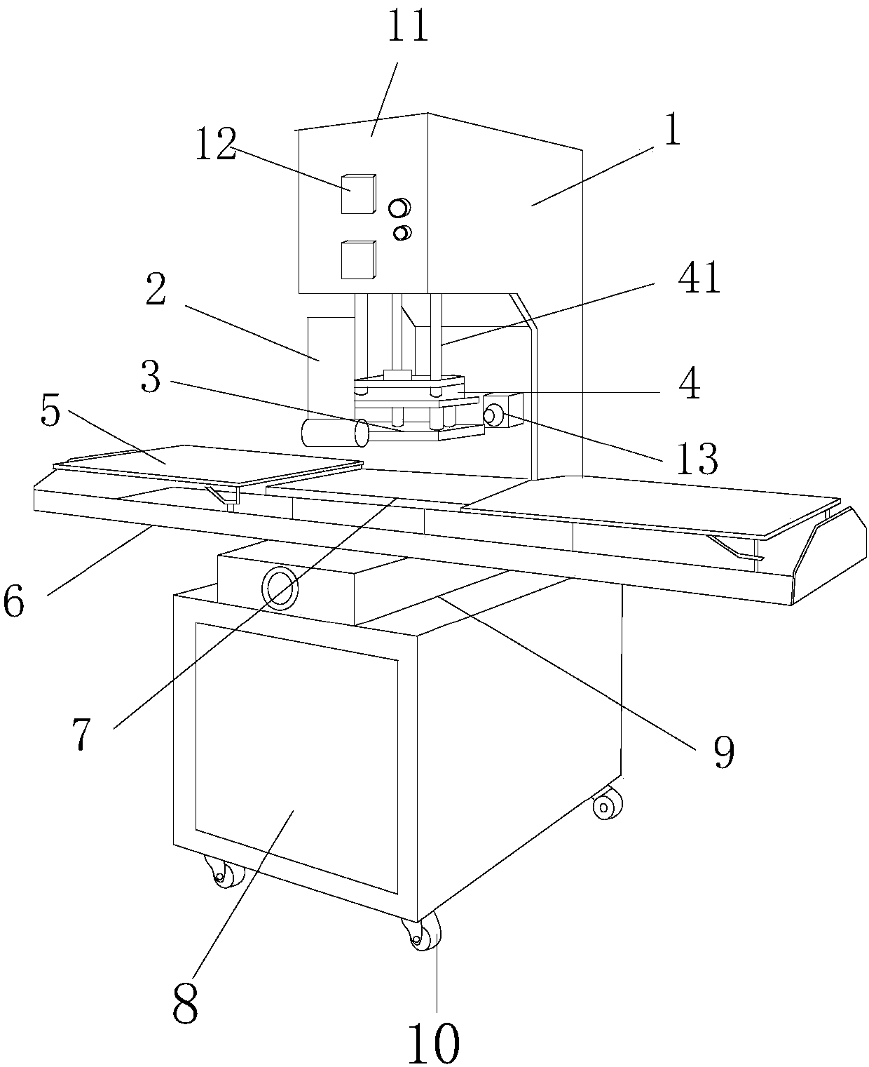
[0023] see Figure 1 to Figure 3, the present invention provides an edge banding machine for toy production, the structure of which includes a power executive seat 1, an edge folding rod 2, an edge banding template 3, a connecting horizontal plate 4, an object conveying backing plate 5, a working platform 6, a positioning sealing Side mold 7, electric control box 8, automatic adjustment and alignment device 9, casters 10, the bottom of the electric control box 8 is movably connected with the casters 10, the tail of the electric control box 8 is fixedly connected with the power executive seat 1 and is perpendicular to each other, The power actuator seat 1 is provided with a control panel 11, an operation switch 12, and an emergency stop key 13. The control panel 11 and the power actuator seat 1 are of an integrated structure, and the operation switch 12 is arranged on the outer layer of the control panel 11. The emergency stop key 13 is embedded in the front end of the power ac...


PUM


Abstract

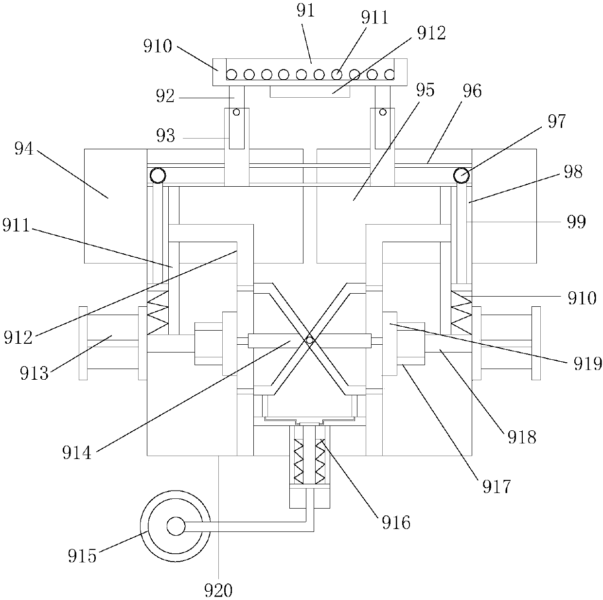
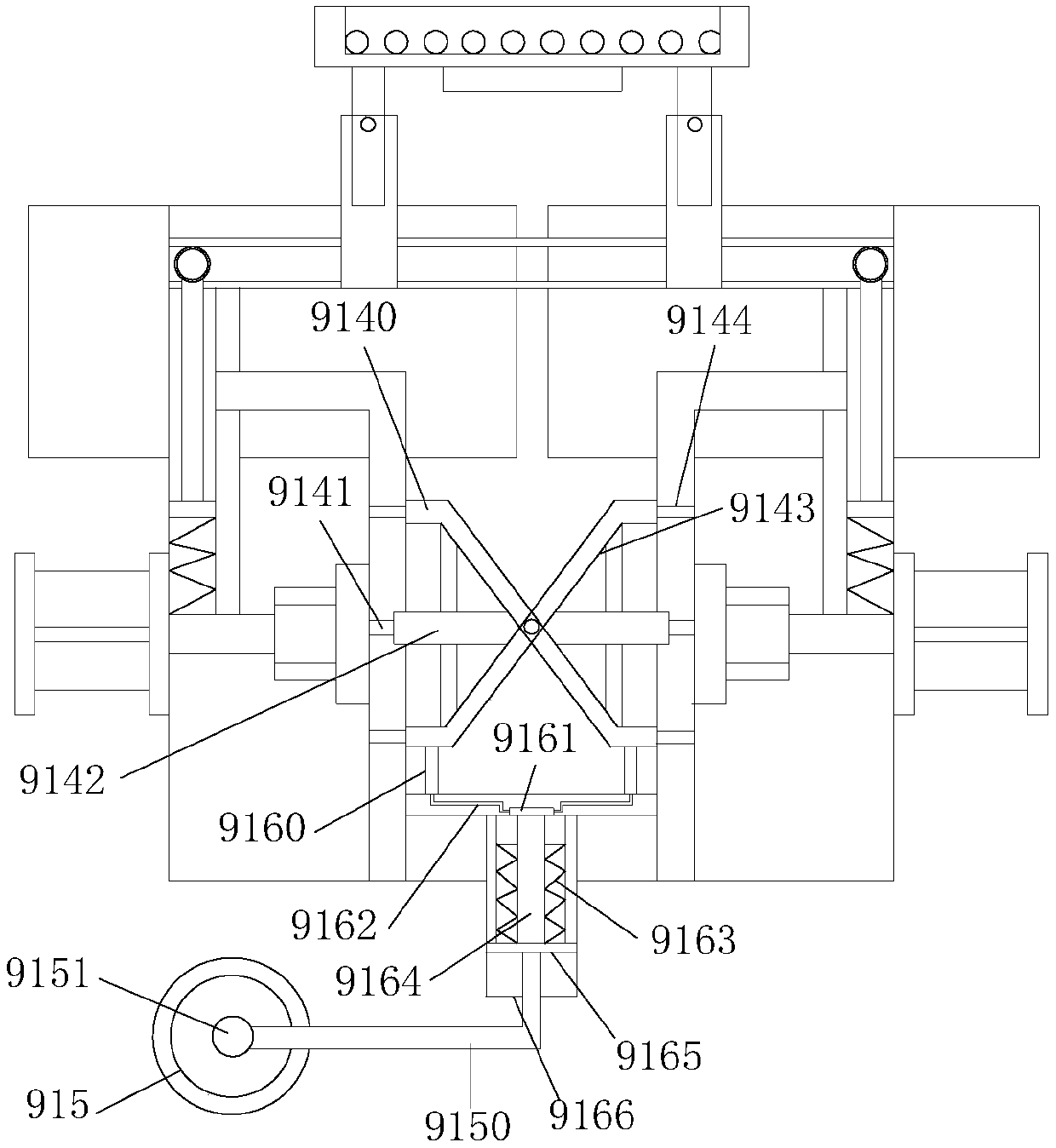
The invention discloses an edge banding machine for toy production. The edge banding machine for toy production structurally comprises a power execution seat, an edge folding rod, an edge banding dieplate, a connection cross plate, an object conveying cushion plate, a working platform, a location edge banding die, an electric control cabinet, an automatic adjustment-alignment device and castors,wherein the bottom of the electric control cabinet is movably connected with the castors; and the tail part of the electric control cabinet is fixedly connected with and mutually vertical to the powerexecution seat. According to the edge banding machine for toy production, a transmission rod is controlled to work for a first-position telescopic displacement rod and a second-position telescopic displacement rod through an adjustment wheel, and horizontal position adjustment can be carried out on a first-position adjustment cushion plate and a second-position adjustment cushion plate under thecooperation of the first-position telescopic displacement rod, the second-position telescopic displacement rod and a balance column, so that simpler and more convenient die adjustment is achieved; meanwhile, adjustment is effectively carried out on the location die at different heights and horizontal positions according to the movement of a lifting column on a slide rail, so that the location accuracy of the edge banding die is improved, and automatic-correction edge banding is realized; and meanwhile, automatic-temperature-control heating can be carried out on an edge banding part, so that the working efficiency is increased.

Description

technical field [0001] The invention relates to an edge banding machine for toy production, which belongs to the technical field of edge banding machines for toy production. Background technique [0002] At present, with the development of productivity and the improvement of science and technology, modern society has gradually entered the fast-paced era of mechanization. Most of people's clothing, food, housing and transportation to daily necessities are made by machinery, and toy production is even more mechanized. The traditional production of toy equipment is generally more efficient and focuses on a certain aspect of production operations. [0003] The edge banding machine is a highly automated machine that replaces the manual process of edge banding: conveying - gluing and pasting - cutting - front and rear alignment - up and down trimming - up and down fine trimming - up and down scraping - polishing, mainly divided into semi-automatic And portable two. [0004] The ...

Claims


Application Information

Patent Timeline
IPC IPC(8): B29C65/20B29C65/78A63H9/00B29L31/52
CPCB29C65/20A63H9/00B29C65/78B29C65/7841B29C65/7858B29L2031/5209
Inventor 黄思珍
Owner 黄思珍
Learn More