Novel electric cylinder

An electric cylinder and electric cylinder technology, which is applied in the direction of electric components, transmission devices, electromechanical devices, etc., can solve the problems that the electric cylinder cannot be miniaturized and the overall structure size is increased.

Active Publication Date: 2020-06-26
深圳市迈胜恒源科技有限公司
View PDF6 Cites 0 Cited by
  • Summary
  • Abstract
  • Description
  • Claims
  • Application Information

AI Technical Summary

Problems solved by technology

[0002] In the existing screw drive, all are sliding table type transmission, the two ends of the screw are fixed, the screw nut is fixed on the sliding table, and the sliding table is fixed on the linear guide rail. After driving the motor, the sliding table realizes linear reciprocating

Method used


Image

  • Novel electric cylinder
  • Novel electric cylinder

Examples


Embodiment 1

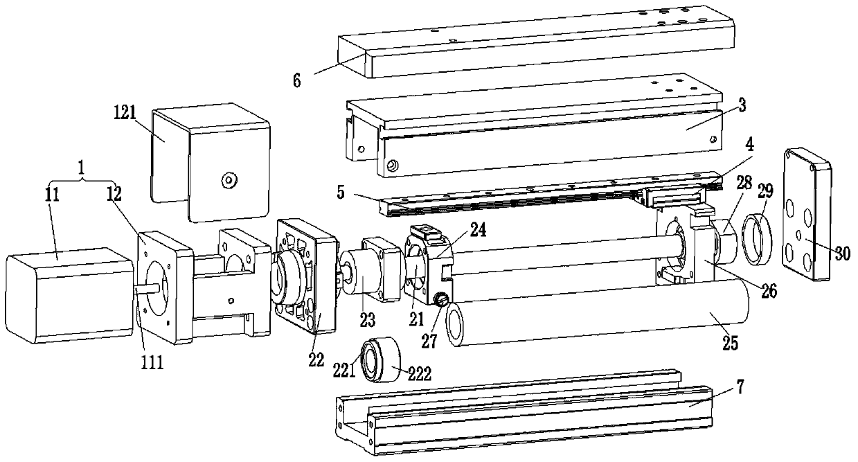
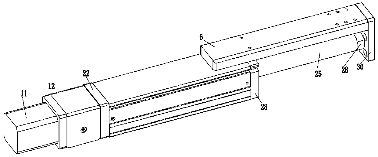
[0024] Such as Figure 1 ~ Figure 2 A new type of electric cylinder shown includes a power assembly 1 and a transmission assembly 2 connected to the output shaft 111 of the power assembly 1;

[0025] In a preferred embodiment of this embodiment, the transmission assembly 2 includes a screw rod 21 fixedly connected to the output shaft 111, a screw rod fixing seat 22 sleeved on one side of the screw rod 21, and a screw nut 23 threadedly connected to the screw rod 21 , Fix the nut fixing seat 24 sleeved on the screw nut 23, and the electric cylinder shaft 25 fixedly installed on the axial end of the nut fixing seat 24, and the electric cylinder support seat 26 sleeved on the other end of the electric cylinder shaft 25; nut fixing seat Fastening bolts 27 are installed on the left and right sides of 24.

[0026] In a preferred embodiment of this embodiment, the fastening bolt 27 is divided into a first fastening bolt 271 on the left side of the nut fixing seat 24 and a second fastening...


PUM


Abstract

The invention discloses a novel electric cylinder. The novel electric cylinder particularly aims at the occasion of using the stretching method. The novel electric cylinder optimizes a transmission structure of a transmission feed screw and fixes a feed screw nut at one end of an electric cylinder shaft. The electric cylinder shaft realizes stretching motion after an electric machine driving the electric cylinder shaft. A limiting ring is placed at the stretching end of the electric cylinder shaft to limit the upper and the lower position of the electric cylinder shaft. By two sets of fastening bolts adjusting slightly the left and the right position of the push-out electric cylinder shaft, the left and the right position pushing out inclined to one side is prevented when the electric cylinder shaft push out.

Description

Technical field [0001] The invention relates to a new type of electric cylinder. Background technique [0002] In the existing screw drive, they are all sliding table transmissions. The two ends of the screw rod are fixed, the screw nut is fixed on the sliding table, and the sliding table is fixed on the linear guide rail. After the motor is driven, the sliding table realizes linear reciprocating motion. However, this transmission structure is a sliding table type. In some occasions where telescopic applications are required, additional connectors are required. However, this will increase the overall structure size and cannot satisfy the miniaturized electric cylinder. Summary of the invention [0003] The present invention aims to solve one of the above technical problems at least to a certain extent. Therefore, the purpose of the present invention is to provide an optimized transmission mode of the electric cylinder so that the electric cylinder can be installed in a narrow spa...

Claims


Application Information

Patent Timeline
IPC IPC(8): F16H25/20H02K7/06
CPCF16H25/20H02K7/06F16H2025/204F16H2025/2075
Inventor 杜与恒
Owner 深圳市迈胜恒源科技有限公司
Why Eureka
Try Eureka