Dismounting method of connecting mechanism convenient to dismount
A connecting mechanism and locking hook technology, applied in mechanical equipment, fixing devices, etc., can solve problems such as inconvenient connection, poor stability, complicated disassembly process, etc., and achieve the effect of twisting and labor saving
- Summary
- Abstract
- Description
- Claims
- Application Information
AI Technical Summary
Problems solved by technology
Method used
Image
Examples
Embodiment 1
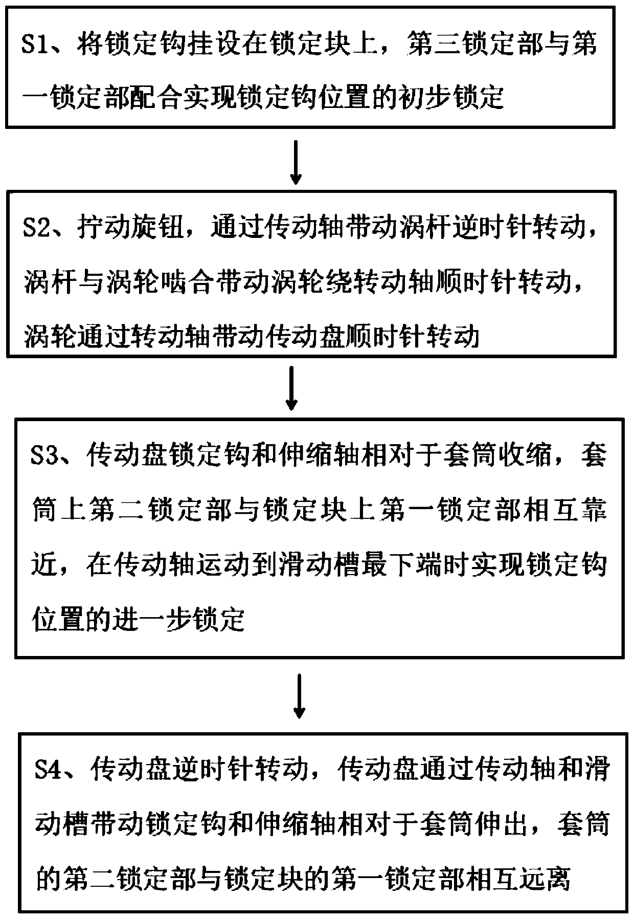
[0030] A dismounting method for a connection mechanism that is easy to disassemble, said dismounting method comprising the following steps:
[0031] S1. Hang the locking hook on the locking block, and the third locking part cooperates with the first locking part to realize preliminary locking of the position of the locking hook.
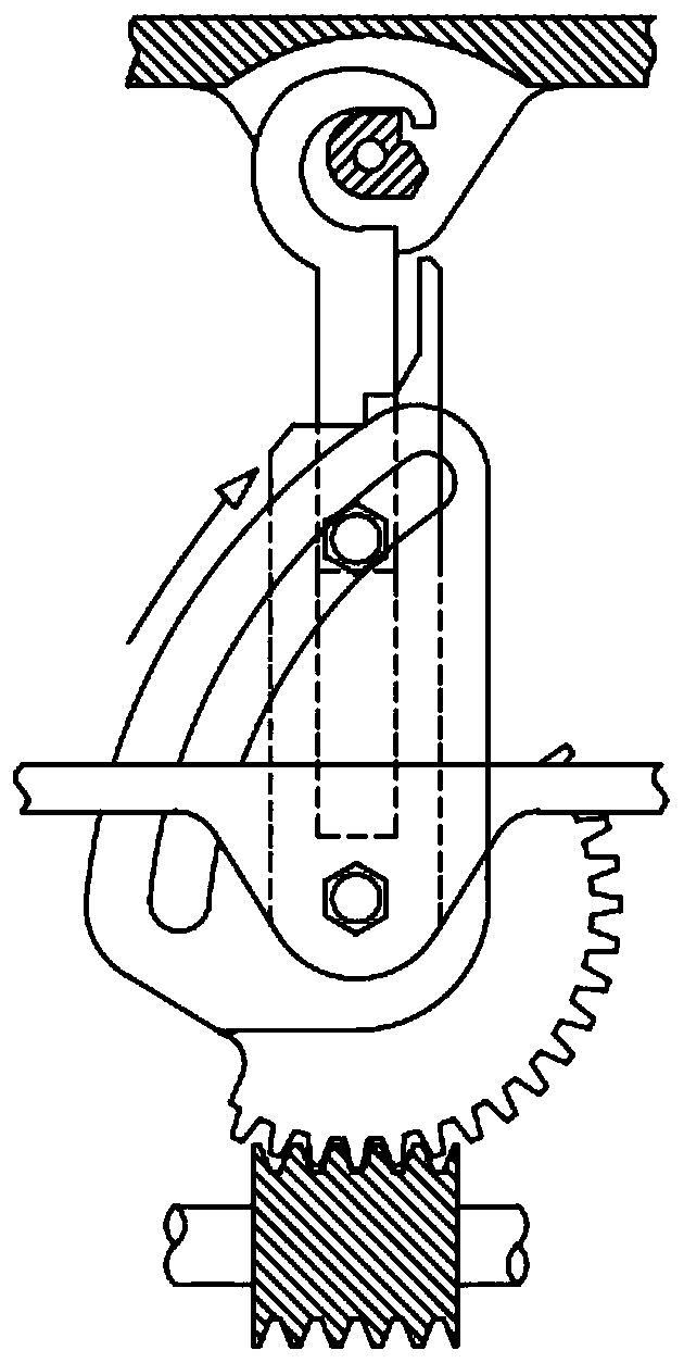
[0032] S2. Turn the knob counterclockwise, the knob drives the worm to rotate counterclockwise through the transmission shaft, the worm meshes with the turbine and drives the turbine to rotate clockwise around the rotation axis, and the turbine drives the transmission disc to rotate clockwise through the rotation shaft.
[0033] S3. The transmission disc drives the locking hook and telescopic shaft to shrink relative to the sleeve through the transmission shaft and sliding groove, and then the second locking part on the sleeve and the first locking part on the locking block are close to each other, and when the transmission shaft moves to slide Furth...
Embodiment 2
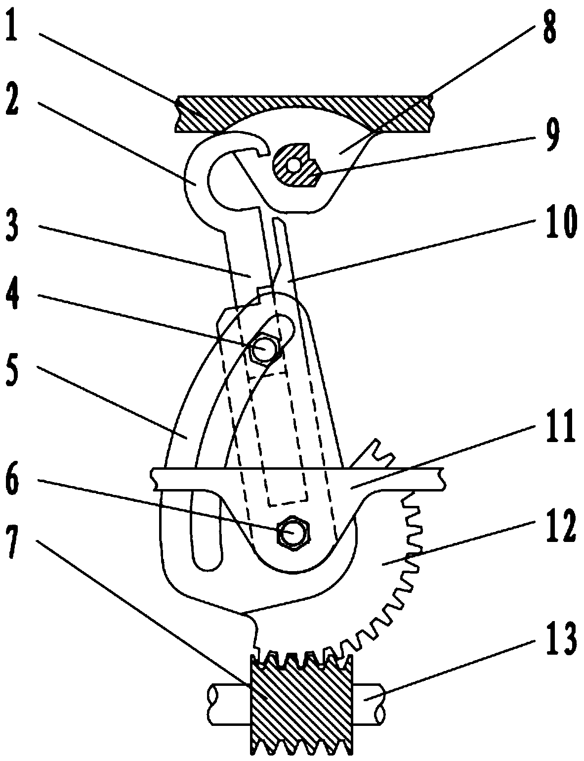
[0038] Such as figure 2 As shown, the present invention also discloses a connection mechanism that is easy to disassemble, including an upper connection plate 1 for positioning the upper connection plate 1 of the locking block 9; a locking hook 2 for locking and connecting with the locking block 9 ; The locking device is used for locking and unlocking the locking hook 2 and the locking block 9 .
[0039] A connecting plate 8 is arranged on the upper connecting plate 1, and a connecting hole is arranged on the connecting plate 8, and the locking block 9 is fixedly connected with a pin shaft, and the pin shaft is arranged in the connecting hole.
[0040] The locking device includes a transmission shaft 13, a worm 7, a turbine 12, a rotating shaft 6, a lower connection plate 11, a sleeve 10, a telescopic shaft 3, a transmission shaft 4 and a transmission disc 5, and the bottom of the upper connection plate 1 is provided with The lower connecting plate 11, the middle part of the...
Embodiment 3
[0050] Such as figure 2 As shown, a connection mechanism that is easy to disassemble includes an upper connection plate 1 for positioning the upper connection plate 1 of the locking block 9; a locking hook 2 for locking and connecting with the locking block 9; a locking device for For the locking and unlocking of the locking hook 2 and the locking block 9.
[0051] A connecting plate 8 is arranged on the upper connecting plate 1, and a connecting hole is arranged on the connecting plate 8, and the locking block 9 is fixedly connected with a pin shaft, and the pin shaft is arranged in the connecting hole.
[0052] The locking device includes a transmission shaft 13, a worm 7, a turbine 12, a rotating shaft 6, a lower connection plate 11, a sleeve 10, a telescopic shaft 3, a transmission shaft 4 and a transmission disc 5, and the bottom of the upper connection plate 1 is provided with The lower connecting plate 11, the middle part of the lower connecting plate 11 is provided w...
PUM
 Abstract
Description
Claims
Application Information
 - R&D Engineer
- R&D Manager
- IP Professional
- Industry Leading Data Capabilities
- Powerful AI technology
- Patent DNA Extraction
Browse by: Latest US Patents, China's latest patents, Technical Efficacy Thesaurus, Application Domain, Technology Topic, Popular Technical Reports.
© 2024 PatSnap. All rights reserved.Legal|Privacy policy|Modern Slavery Act Transparency Statement|Sitemap|About US| Contact US: help@patsnap.com


