
Medical evaporative suction device

An evaporative and equipment technology, which is applied in the field of medical evaporative inhalation equipment, can solve problems such as easy backflow to damage the electrode, waste of atomized liquid medicine, etc., and achieve the effects of cost saving, convenient inhalation operation, and avoiding natural evaporation

Active Publication Date: 2020-07-14
帕夫全球战略有限责任公司
View PDF6 Cites 0 Cited by
  • Summary
  • Abstract
  • Description
  • Claims
  • Application Information

AI Technical Summary

Problems solved by technology

[0004] The main purpose of the present invention is to propose a medical evaporative inhalation device, which aims to solve the technical problems of the existing inhalation device that the atomized liquid is wasted, and the atomized gas is easy to flow back and damage the electrode after condensation

Method used


Image

  • Medical evaporative suction device
  • Medical evaporative suction device
  • Medical evaporative suction device

Examples


Embodiment Construction

[0037] The following will clearly and completely describe the technical solutions in the embodiments of the present invention with reference to the accompanying drawings in the embodiments of the present invention. Obviously, the described embodiments are only part of the embodiments of the present invention, not all of them. Based on the embodiments of the present invention, all other embodiments obtained by persons of ordinary skill in the art without creative efforts fall within the protection scope of the present invention.

[0038] It should be noted that if there are directional indications such as up, down, left, right, front, back, etc. in the embodiment of the present invention, the directional indications are only used to explain the position of each individual in a certain posture as shown in the attached figure. If the relative positional relationship, movement conditions, etc. between the components change, the directional indication will also change accordingly. ...


PUM


Abstract

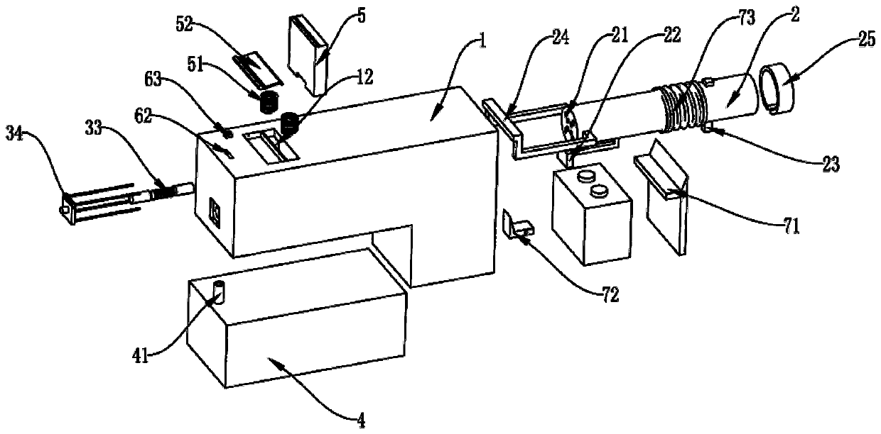
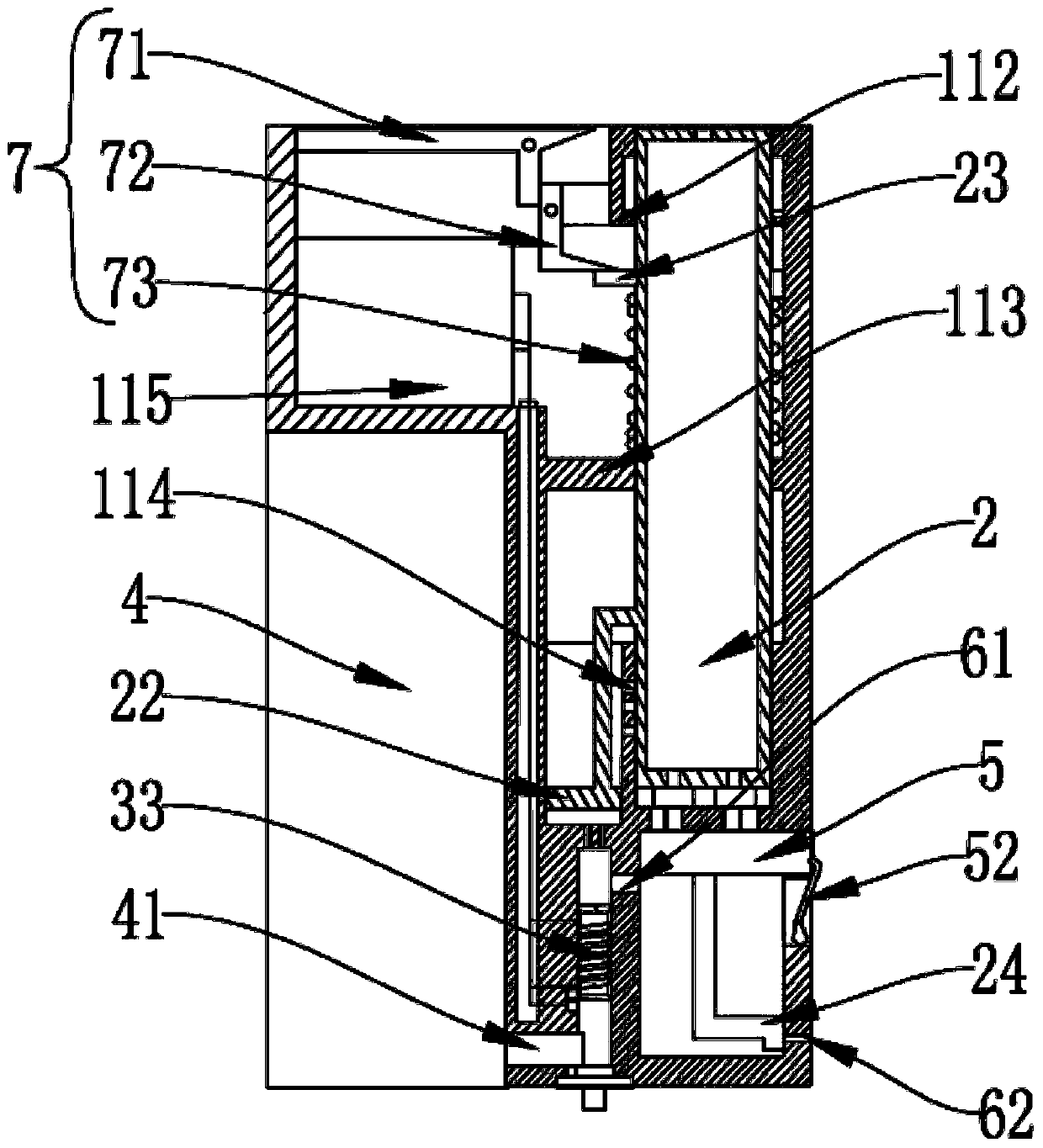
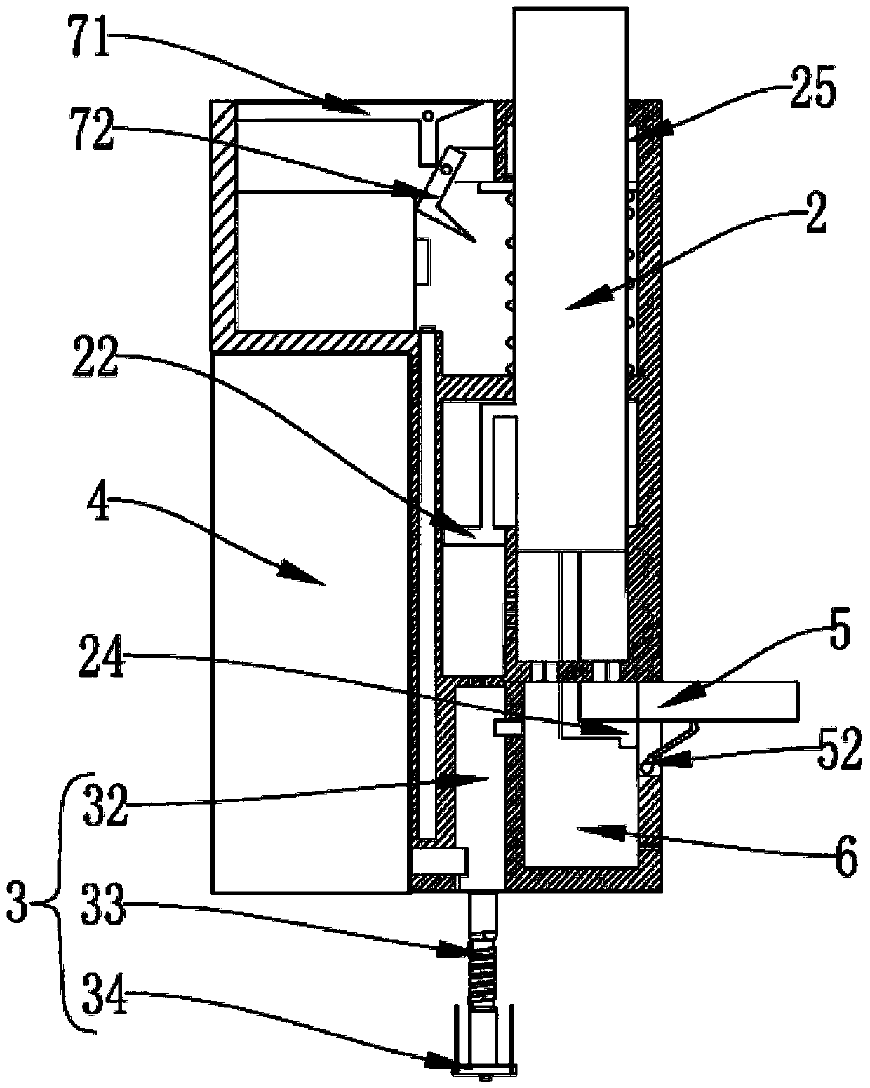
The invention discloses a medical evaporative suction device. The medical evaporative suction device comprises a shell, a suction nozzle, an atomization unit and a liquid storage cavity, wherein an accommodating cavity is formed in the shell; the suction nozzle is arranged in the accommodating cavity and can move up and down along the accommodating cavity; a first air inlet channel is formed in the bottom end of the suction nozzle; the atomization unit communicates with the accommodating cavity through a second air inlet channel; the liquid storage cavity communicates with the atomization unitthrough a liquid inlet channel; a first plugging piece for plugging the second air inlet channel is arranged on the outer wall of the suction nozzle; a condensation chamber is arranged at the lower end of the accommodating cavity; the accommodating cavity communicates with the condensation chamber through a backflow channel; and an air inlet cavity is formed in the lower end of the condensation chamber and is connected with the atomization unit through a third air inlet channel. By arrangement of a pop-up device, the suction nozzle can be in a pop-up state and a retracting state, the medicalevaporative suction device is convenient to operate, atomized gas can be directly sucked by the suction nozzle, waste is avoided, and the condensed atomized gas is collected by the condensation chamber and cannot flow back into the device to damage other assemblies.

Description

technical field [0001] The invention relates to the technical field of inhalation equipment, in particular to a medical evaporative inhalation equipment. Background technique [0002] The existing steam inhaler heats the medicinal liquid to make it into steam, which is inhaled by the user from the respiratory tract to achieve therapeutic purposes. It has been widely used in the alleviation of various diseases, such as: reducing inflammation and edema of the respiratory tract; promoting local Blood circulation; relieve bronchospasm, dilute respiratory secretions; reduce respiratory irritation and relieve cough. [0003] However, the current steam inhalation device usually uses steam to aim at the user's face, and then the user inhales the atomized liquid medicine. In this way, there is a lot of waste of the atomized liquid medicine, and the user's face is sprayed with the liquid medicine during use. It is soaked, and the face needs to be washed after use, and the use process...

Claims


Application Information

Patent Timeline
IPC IPC(8): A61M15/00
CPCA61M15/00A61M15/0021
Inventor 不公告发明人
Owner 帕夫全球战略有限责任公司
Learn More