A high-pressure hole sealing and pressure maintaining and releasing device for coal and rock formations

A pressure relief device, a technology for coal and rock formations, used in wellbore/well valve device, sealing/isolation, wellbore/well components, etc. problems, to achieve the effect of facilitating the promotion and use

Active Publication Date: 2022-03-18
XIAN UNIV OF SCI & TECH +1
View PDF18 Cites 0 Cited by
  • Summary
  • Abstract
  • Description
  • Claims
  • Application Information

AI Technical Summary

Problems solved by technology

When the water injection is stopped or the pump is accidentally stopped, the pressure in the hole sealed by the existing hole sealer is much greater than the pressure in the high-pressure rubber expansion hose, and the high-pressure rubber expansion hose is ejected from the hole due to insufficient sealing pressure, causing great problems. Once the operator is at the drilling position, the consequences will be unimaginable after stopping the water injection, and the huge impact force and impact speed will cause the sealing rubber outside the high-pressure rubber expansion hose to be damaged by the friction of the drilling hole, and the sealing effect will be poor when used again. The service life is short, and the existing sealing method cannot achieve effective and controllable pressure relief for the high-pressure water in the borehole

Method used


Image

  • A high-pressure hole sealing and pressure maintaining and releasing device for coal and rock formations
  • A high-pressure hole sealing and pressure maintaining and releasing device for coal and rock formations
  • A high-pressure hole sealing and pressure maintaining and releasing device for coal and rock formations

Examples


Embodiment Construction

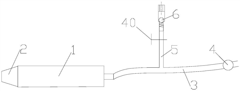
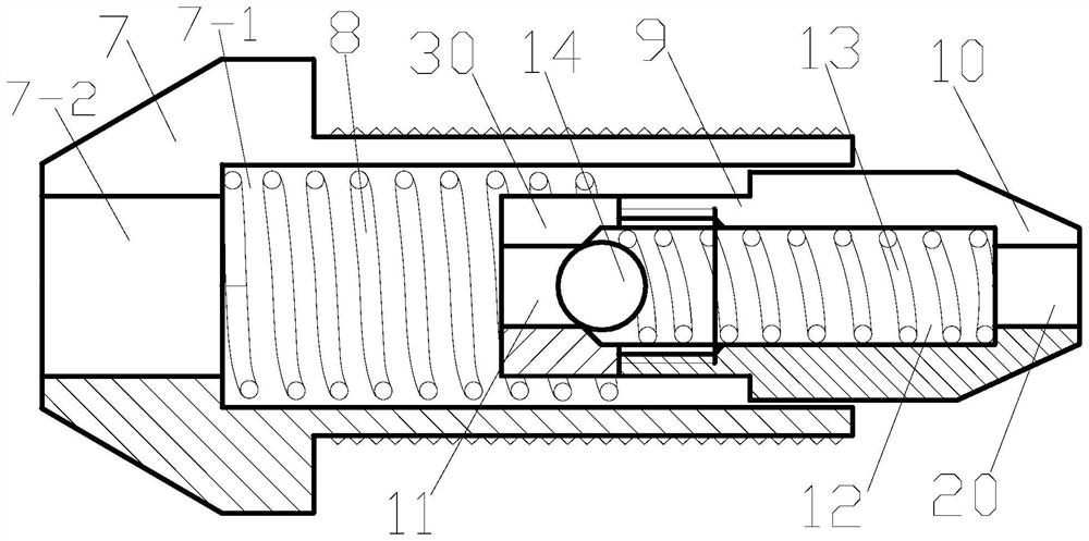
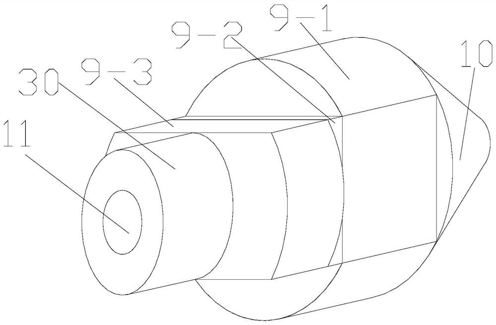
[0029] like Figure 1-Figure 4 As shown, the present invention includes a hole sealing device and a high-pressure water injection pipe 3 connected to the quick connector on the rear side of the hole sealing device. A check valve 4 is installed on the high-pressure water injection pipe 3. The hole sealing device includes a high-pressure rubber expansion The rubber hose 1 and the two-way safety valve 2 arranged at the front end of the high-pressure rubber expansion hose 1, the two-way safety valve 2 includes a hollow structure safety valve head 7 matched with the high-pressure rubber expansion hose 1, and a first spring 8 arranged in the safety valve head 7 And extend into the first spring 8 and is a two-way safety valve core with a hollow structure, the two-way safety valve core includes a safety valve core 9, a safety valve core of a hollow structure that is arranged at one end of the safety valve core 9 and cooperates with the first spring 8 The spool cover 30 and the hollow ...


PUM


Abstract

The invention discloses a high-pressure hole sealing and pressure-maintaining and pressure-relieving device for coal and rock formations, which comprises a hole sealing device and a high-pressure water injection pipe connected with a quick connector on the rear side of the hole sealing device. A check valve and a hole sealing device are installed on the high-pressure water injection pipe. It includes a high-pressure rubber expansion hose and a two-way safety valve arranged at the front end of the high-pressure rubber expansion hose. The two-way safety valve includes a hollow-structure safety valve head matched with the high-pressure rubber expansion hose, a first spring arranged in the safety valve head and extending into the Bi-directional safety spool in primary spring. In the present invention, the one-way safety valve is transformed into a two-way safety valve to meet the requirements of conventional high-pressure water injection into the borehole, and at the same time, the pressure of the pipeline that stops water injection is relieved step by step through the pressure regulating valve in the external pipeline, and the fracturing hole The medium and high pressure water can flow out through the two-way safety valve to realize the in-situ pressure maintenance and relief of the hole sealer, ensuring that the high-pressure rubber expansion hose is not easy to pop out of the drill hole, avoiding high-speed friction with the fracturing hole, and prolonging the service life of the hole sealer. And eliminate potential safety hazards.

Description

technical field [0001] The invention belongs to the technical field of fracturing and sealing holes in coal and rock formations, and in particular relates to a high-pressure hole sealing and pressure maintaining and releasing device for coal and rock formations. Background technique [0002] Accidents such as gas ejection, coal and gas outburst, gas explosion, and rock burst occur from time to time in our country. Coal formation water injection, coal formation hydraulic fracturing and other technologies are effective means to prevent and control gas disasters and rock burst disasters. Safe and effective hole sealing is the primary condition for efficient water injection and hydraulic fracturing. The conventional sealing method is to inject high-pressure water into the high-pressure rubber expansion hose, and the high-pressure rubber expansion hose expands and presses the hole wall to seal the hole. After the water in the high-pressure rubber expansion hose reaches a certain...

Claims


Application Information

Patent Timeline
Patent Type & Authority Patents(China)
IPC IPC(8): E21B43/26E21B34/08E21B33/126
CPCE21B43/261E21B34/08E21B33/126E21B33/1208
Inventor 邓广哲朱徽贾光明胡健
Owner XIAN UNIV OF SCI & TECH
Why Eureka
Try Eureka