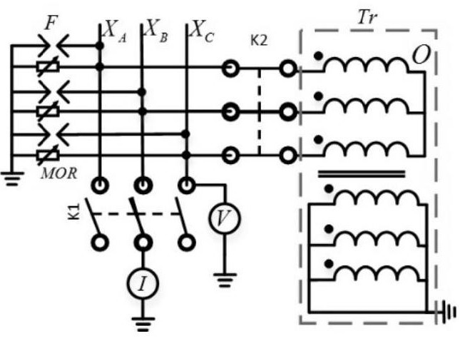
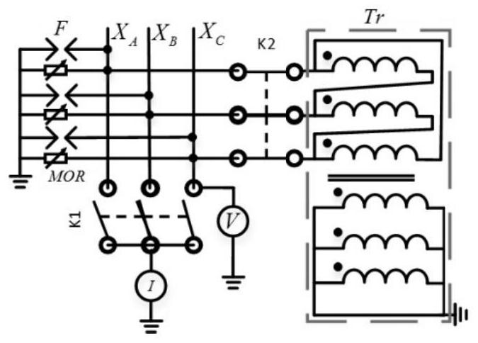
A transformer-shaped neutral point grounding device and method for direct-blocking secondary-side short-circuit

A neutral point grounding and grounding device technology, which is applied in the direction of circuit devices, emergency protection circuit devices, emergency protection circuit devices for limiting overcurrent/overvoltage, etc., can solve the DC current direction deviation, difficult to realize, Current transfer and other issues, to achieve the effects of DC bias suppression, wide application range, and minimized impact

Active Publication Date: 2022-05-06
ELECTRIC POWER RESEARCH INSTITUTE, CHINA SOUTHERN POWER GRID CO LTD
View PDF6 Cites 0 Cited by
  • Summary
  • Abstract
  • Description
  • Claims
  • Application Information

AI Technical Summary

Problems solved by technology

However, in the specific application of this method, first of all, the AC and DC voltage and AC current that the resistor needs to withstand must be considered, which has high requirements for the withstand voltage and heat capacity of the resistor connected in series; secondly, the neutral point series resistance changes. The system structure is broken, and the DC inflow from the neutral point cannot be completely offset, and the relay protection and automation devices need to be re-adjusted; in addition, in order to meet the current limiting requirements, the resistance of the installed current limiting resistor should be large enough, but the large resistor in series cannot Ensure reliable grounding of the system. If the resistor is bypassed with a discharge gap during a fault, the grounding impedance of the system will be discontinuous
[0005] However, the reverse current injection method often causes a shift in the direction of the DC current due to changes in the operation mode of the substation, and the injected reverse current cannot be adjusted at any time, so the effect is not good.
At present, the reverse injection current method is only used in substations where the current exceeds the standard. It requires a larger power supply, and the connection method is more complicated, so it is not easy to implement quickly on site.
The device for realizing the reverse current injection method is complicated, the cost is high, and the realization is difficult
[0006] Capacitive DC blocking method may cause the current to be cut off in one place, but the current in other places is significantly increased, and the phenomenon of current transfer occurs; in addition, the capacitor DC blocking method changes the zero-sequence impedance of the system. Relay protection, automation devices and insulation coordination, etc. All aspects need to be rechecked and set, and there is a danger of explosion under the impact of high current. Its economy and practicability are lacking.
[0007] To sum up, the current mainstream schemes have certain limitations in suppressing DC bias, and it is urgent to optimize and develop an A New Device for Suppressing DC Bias

Method used


Image

  • A transformer-shaped neutral point grounding device and method for direct-blocking secondary-side short-circuit
  • A transformer-shaped neutral point grounding device and method for direct-blocking secondary-side short-circuit
  • A transformer-shaped neutral point grounding device and method for direct-blocking secondary-side short-circuit

Examples


Embodiment Construction

[0035] In order to enable those skilled in the art to better understand the solutions of the present invention, the following will clearly and completely describe the technical solutions in the embodiments of the present invention in conjunction with the drawings in the embodiments of the present invention. Obviously, the described embodiments are only The embodiments are a part of the present invention, not all embodiments, and are not intended to limit the scope of the present invention. Also, in the following description, descriptions of well-known structures and techniques are omitted to avoid unnecessarily obscuring the concepts disclosed in the present invention. Based on the embodiments of the present invention, all other embodiments obtained by persons of ordinary skill in the art without making creative efforts shall fall within the protection scope of the present invention.

[0036] Various structural schematic diagrams according to the disclosed embodiments of the p...


PUM


Abstract

The invention discloses a transformer-shaped neutral point grounding device and a method for direct-blocking and secondary-side short-circuiting. The input end is connected to the low potential end of the three-phase winding of the quasi-star connection of the grid transformer or voltage transformer, and the output end is grounded. The transformer of the device is a three-phase form, the primary side is connected in star or delta, and the secondary side is short-circuited to ground. When it is detected that the output end flows through DC or exceeds the limit value, the transformer of the device operates and isolates the DC, and the input three-phase AC is equivalent to a neutral point current through the short-circuit impedance of the transformer and is grounded; when it is detected that there is no DC at the input end of the device When the voltage is lower than the limit value, the input terminal is connected to the output terminal, the transformer of the device is out of operation, and the three-phase AC input by the device forms a neutral point AC and is grounded. The discharge gap of the device and the zinc oxide resistance suppress the overvoltage generated by the device failure and the like. The method can effectively restrain the DC bias magnetism and ensure the stable operation of the grid transformer and the voltage transformer.

Description

【Technical field】 [0001] The invention belongs to the technical field of high-voltage testing, and relates to a transformer-shaped neutral-point grounding device and method for direct-blocking and secondary-side short-circuiting. 【Background technique】 [0002] In order to ensure the safe operation of the power grid, it is urgent to study the measures to suppress the DC bias of the power grid. [0003] The current mainstream methods for suppressing DC bias are resistor current limiting method, reverse current injection method, and capacitor DC blocking method. However, they all have certain problems in practical engineering applications. [0004] Although the concept of the resistance current limiting method is clear, it is relatively cheap and easy to implement. However, in the specific application of this method, first of all, the AC and DC voltage and AC current that the resistor needs to withstand must be considered, which has high requirements for the withstand voltag...

Claims


Application Information

Patent Timeline
Patent Type & Authority Patents(China)
IPC IPC(8): H02H9/00H02H7/04H02H7/05G01R19/165
CPCH02H9/002H02H7/04H02H7/05G01R19/165
Inventor 王国利陈承罗兵罗勇芬王婷婷廖一帆贾磊
Owner ELECTRIC POWER RESEARCH INSTITUTE, CHINA SOUTHERN POWER GRID CO LTD
Why Eureka
Try Eureka