A new type of installation and fixation method for transformer DC bias suppression device

A technology of DC bias suppression and fixing method, which is applied in the directions of transformer/reactor installation/support/suspension, transformer/inductor noise damping, circuit devices, etc., and can solve the problems of increased vibration, increased transformer noise, and increased transformer loss, etc. problem, to achieve the effect of reducing vibration

Inactive Publication Date: 2020-01-17
STATE GRID XINJIANG ELECTRIC POWER CO ECONOMIC TECH RES INST +3
View PDF6 Cites 0 Cited by
  • Summary
  • Abstract
  • Description
  • Claims
  • Application Information

AI Technical Summary

Problems solved by technology

When the transformer generates DC bias, it will cause increased transformer noise, increased vibration, local overheating, and increased transformer loss.
[0003] The new installation and fixing method of the existing transformer DC bias suppression device cannot comprehensively consider the installation and selection of transformer equipment

Method used


Image

  • A new type of installation and fixation method for transformer DC bias suppression device
  • A new type of installation and fixation method for transformer DC bias suppression device
  • A new type of installation and fixation method for transformer DC bias suppression device

Examples


Embodiment 1

[0042] Embodiment 1: A novel installation and fixing method of a transformer DC bias suppression device, comprising the following steps;

[0043] S1. Establish a power system model, and record the data of each substation in the line to which the transformer DC bias suppression device belongs;

[0044] S2. According to the design requirements, collect the geographical information of the installation place of the DC bias suppression device of the transformer, and upload the design data of each item to the corresponding power system model;

[0045] S3. According to the geographic information of the installation site in S1, find out the historical records of solar storms in the region, take the largest solar storm value in the area of ​​the installation site over the years and import it into the power system model for calculation, and then judge the potential gradient induced by the surface potential gradient in the transformer winding The influence of geomagnetic induction curren...

Embodiment 2

[0051] Embodiment 2: refer to Figure 5 , combined with the basis of Embodiment 1, the difference lies in that a novel installation and fixing method of a transformer DC bias suppression device, in calculating the DC current of each transformer winding in S5, the following formula needs to be used for calculation;

[0052]

[0053] In the formula: Uab is the linear potential difference between the neutral point grounding of two transformers a and b; R a , R b is the transformer grounding resistance of transformer a and b; R 1 is the resistance of each phase of the line between two transformers a and b; i ab is the DC current of each transformer winding.

[0054] In S5, the estimation of the DC capacity of the transformer is selected based on the DC current of each transformer winding satisfying the following conditions;

[0055] i ab ≤2i 空载

[0056] In the formula: i 空载 is the excitation current under no-load condition, i ab is the DC current of each transformer wi...

Embodiment 3

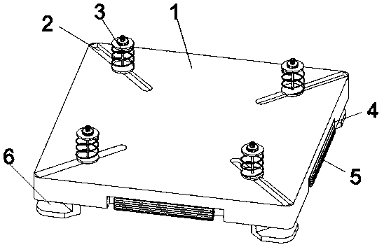
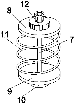
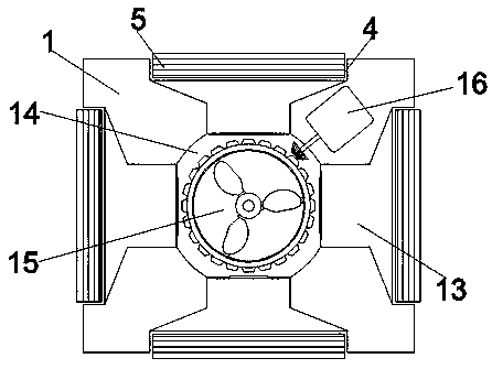
[0059] Embodiment 3: A new installation and fixing device of a transformer DC bias suppression device, which is applied to a new installation and fixing method of a transformer DC bias suppression device, including a base 1 and a buffer seat 3, and also includes a dust removal grid 5 and a suction device 15. The four corners of the upper surface of the base 1 are provided with slide rails 2, the bottom of the buffer seat 3 is slidingly connected with the slide rails 2, the middle of the four sides of the base 1 is provided with an installation groove 4, and the dust removal grille 5 is fixedly installed in the installation groove 4, and the base 1 There is a dust suction chamber 14 in the center of the interior, a dust suction pipe 13 is fixedly connected between the dust suction chamber 14 and the dust removal grille 5, a suction device 15 is fixedly installed inside the dust suction chamber 14, and a motor is fixedly installed inside the base 1 16. The output shaft of the mot...


PUM


Abstract

The invention discloses a novel mounting and fixing method for a transformer direct-current magnetic bias suppression device, and belongs to the field of direct-current magnetic bias suppression devices. According to the novel mounting and fixing method for the transformer DC magnetic bias suppression device, direct-current magnetic bias generation reasons are mainly divided into three kinds, namely geomagnetic current caused by solar storm, in-ground direct current generated by operation of a direct current power transmission single-pole loop and direct current components generated by an asymmetric load, by building an electric power system model, and the three kinds of reasons are fully considered; the generation probability of direct-current magnetic bias is reduced from the source, economic technical schemes of various methods for inhibiting direct-current magnetic bias are calculated in combination with several methods for inhibiting direct-current magnetic bias, decision makers can compare and select the most suitable transformer equipment, and finally, the transformer equipment is mounted.

Description

technical field [0001] The invention relates to the field of DC bias suppression devices, in particular to a novel installation and fixing method for a transformer DC bias suppression device. Background technique [0002] DC bias refers to an abnormal working state of the transformer, which means that a DC component appears in the excitation current of the transformer. There are many reasons for the generation of DC bias, and the solar magnetic storm is one of them. DC bias will cause the temperature of the transformer to rise, the noise will increase, and the vibration will increase. Attention must be paid to the operation of the transformer. In the process of high-voltage direct current transmission, there are two reasons for the generation of DC bias current. One is the geomagnetic induction current generated by the solar magnetic storm. The frequency of this geomagnetic induction current is very low. In general, the geomagnetic induction current The frequency is 0.01-0....

Claims


Application Information

Patent Timeline
Patent Type & Authority Patents(China)
IPC IPC(8): H02H9/00H02H9/02H01F27/06H01F27/33
Inventor 张增强王洪涛余中平荆世博陈伟伟赵志强李海峰辛超山任娟付高善周专薛静杰纪凤坤王新刚孙立成刘奎余金郭太平于国康李静雅高贵亮穆峰磊徐景凡吴伟丽刘勇刘俊
Owner STATE GRID XINJIANG ELECTRIC POWER CO ECONOMIC TECH RES INST
Why Eureka
Try Eureka