
Bridge anti-collision protection device and using method thereof

A protection device and anti-collision technology, which is applied in bridges, bridge parts, bridge construction, etc., can solve problems such as weak anti-collision ability, high cost, and complex structure

Inactive Publication Date: 2020-08-07
中水电四局南方(珠海)工程有限公司
View PDF7 Cites 2 Cited by
  • Summary
  • Abstract
  • Description
  • Claims
  • Application Information

AI Technical Summary

Problems solved by technology

[0002] With the development of society, most of the means of transportation for people to travel choose cars, but with the increase in the number of cars, the traffic hazards continue to increase, and roads are areas where traffic accidents frequently occur, so the road bridge anti-collision device is particularly important However, most of the existing anti-collision devices for highway bridges have weak anti-collision capabilities, complex structures, are easily damaged, and the cost of maintenance and replacement is high. Therefore, we need a bridge anti-collision protection device to solve the above problems and meet people's needs.

Method used


Image

  • Bridge anti-collision protection device and using method thereof
  • Bridge anti-collision protection device and using method thereof
  • Bridge anti-collision protection device and using method thereof

Examples


Embodiment 1

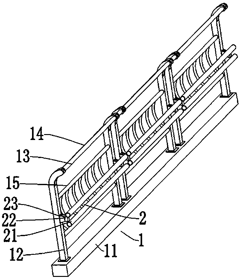
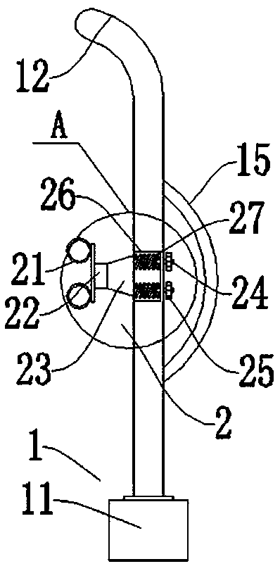
[0028] like Figure 1-Figure 4 As shown, a bridge anti-collision protection device includes a support mechanism 1. The support mechanism 1 includes a concrete pier 11 and several groups of column units. Above, the first crossbar 13 is fixedly installed on the column 12, and the second crossbar 14 is fixedly installed below the first crossbar 13 on the column 12, and a protective bar 15 is installed between the two columns 12 of the same group. 12 is positioned at the front side of protective rod 15 and is equipped with the buffer mechanism 2 that is used for buffering the bridge impact force.

[0029] Preferably: the buffer mechanism 2 includes a round bar 21 arranged horizontally, a buffer box 22 and a bracket 23, the bracket 23 is fixed on the inner side wall of the column 12, the buffer box 22 is fixedly installed on the inner side wall of the bracket 23, and the round bar 21 is fixed on the buffer On the inner side wall of the box 22, the rear end of the bracket 23 is fix...

Embodiment 2

[0031] like Figure 5-Figure 7 As shown, a bridge anti-collision protection device includes a support mechanism 1. The support mechanism 1 includes a concrete pier 11 and several groups of column units. Above, the first crossbar 13 is fixedly installed on the column 12, and the second crossbar 14 is fixedly installed below the first crossbar 13 on the column 12, and a protective bar 15 is installed between the two columns 12 of the same group. 12 is positioned at the front side of protective rod 15 and is equipped with the buffer mechanism 2 that is used for buffering the bridge impact force.

[0032] Preferably: the buffer mechanism 2 includes a second groove 28 provided on the inner side wall of the column 12 along the length direction of the column 12 and a second shaft 213 installed in the second groove 28, the second shaft 213 extends along the length of the column 12 The direction is fixedly installed in the second groove 28, and the second shaft rod 213 is slidingly sl...


PUM


Abstract

The invention discloses a bridge anti-collision protection device and a using method thereof. The device includes a supporting mechanism, the supporting mechanism comprises a concrete pier and a plurality of sets of stand column units, each stand column unit is composed of two stand columns, the stand columns are fixedly installed above the concrete pier, a first cross rod is fixedly installed onthe stand columns, a second cross rod is fixedly installed on the stand columns and located below the first cross rod, a protection rod is installed between the two stand columns in the same set, anda buffer mechanism used for buffering impact force generated by impacting a bridge is installed on the stand columns and located on the front side of the protection rod. The buffer mechanism is arranged, and vehicle impact force is buffered and protected through the buffer mechanism, so a good protection effect can be achieved, the situation that impact between a vehicle and a highway bridge is too serious is avoided; and the buffer mechanism is simple in structure, convenient to install and manufacture, low in manufacturing and maintenance cost and high in practicability and is made of existing common materials.

Description

technical field [0001] The invention relates to the technical field of bridge engineering, in particular to a bridge anti-collision protection device and an application method thereof. Background technique [0002] With the development of society, most of the means of transportation for people to travel choose cars, but with the increase in the number of cars, the traffic hazards continue to increase, and roads are areas where traffic accidents frequently occur, so the road bridge anti-collision device is particularly important However, most of the existing anti-collision devices for highway bridges have weak anti-collision capabilities, complex structures, are easily damaged, and the cost of maintenance and replacement is high. Therefore, we need a bridge anti-collision protection device to solve the above problems and meet people's needs. . Contents of the invention [0003] The object of the present invention is to provide a bridge anti-collision protection device and ...

Claims


Application Information

Patent Timeline
Patent Type & Authority Applications(China)
IPC IPC(8): E01D19/00E01D19/02E01F15/14
CPCE01D19/00E01D19/02E01F15/141
Inventor 杨延辉杨应科秦光磊吴金虎马良于松聆姚振民李根
Owner 中水电四局南方(珠海)工程有限公司
Learn More