Liquid ejecting apparatus
一种喷射装置、液体喷射头的技术,应用在着墨装置、打印装置、印刷等方向,能够解决压力压力控制复杂等问题
- Summary
- Abstract
- Description
- Claims
- Application Information
AI Technical Summary
Problems solved by technology
Method used
Image

Examples
no. 1 approach
[0020] Hereinafter, a first embodiment of a recording device including a liquid ejecting device will be described with reference to the drawings.
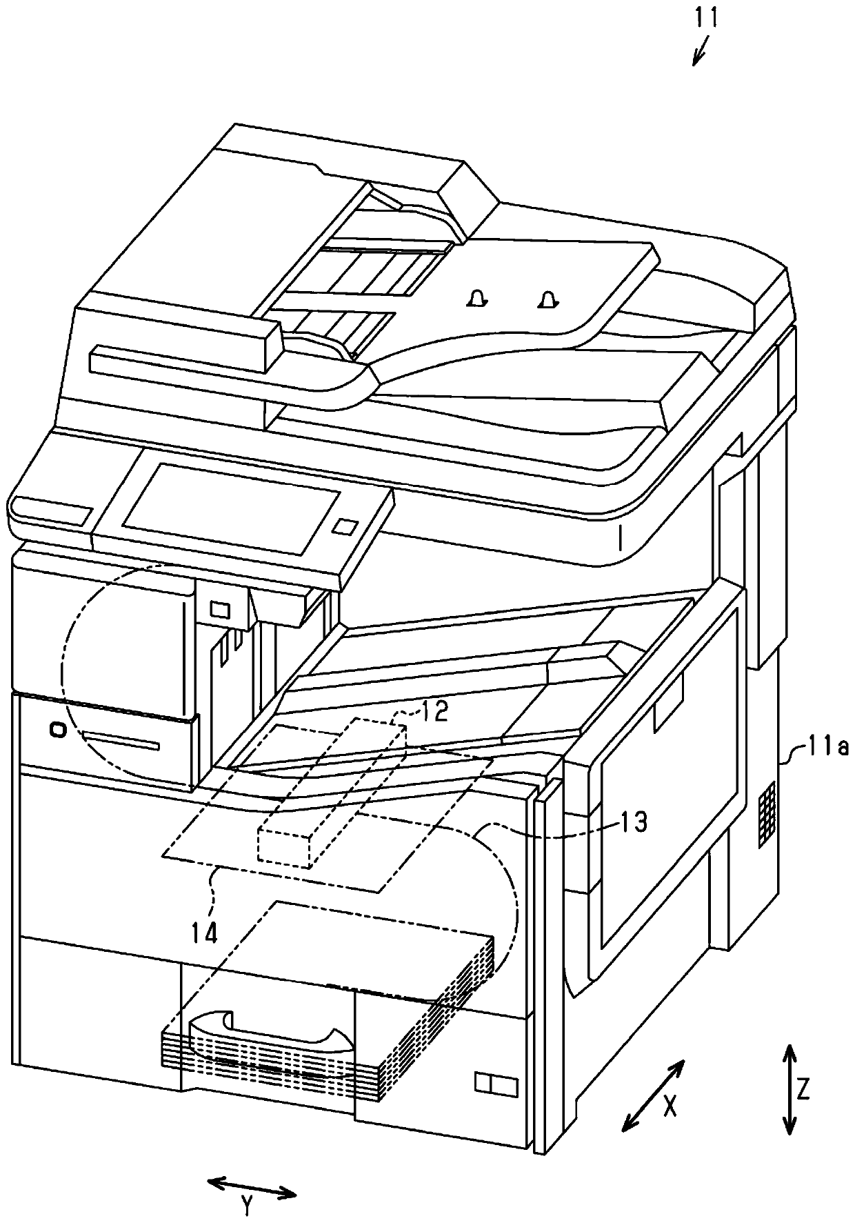
[0021] Such as figure 1 As shown, the recording device 11 includes a liquid ejecting device 11 a and has a substantially rectangular parallelepiped shape long in the vertical direction Z as a whole. The vertical direction Z is the direction of gravity. The liquid ejecting device 11 a includes a liquid ejecting unit 12 capable of ejecting ink as an example of a liquid. The liquid ejection unit 12 executes recording by ejecting liquid onto the paper 14 conveyed along the conveyance path 13 indicated by the dashed-two dotted line in the figure. In the present embodiment, the liquid ejection unit 12 is a so-called line head capable of simultaneously ejecting ink across the width direction X of the paper 14 . In addition, the width direction X is a direction along the conveyance area where the paper 14 is conveyed, and is a direction...
no. 2 approach
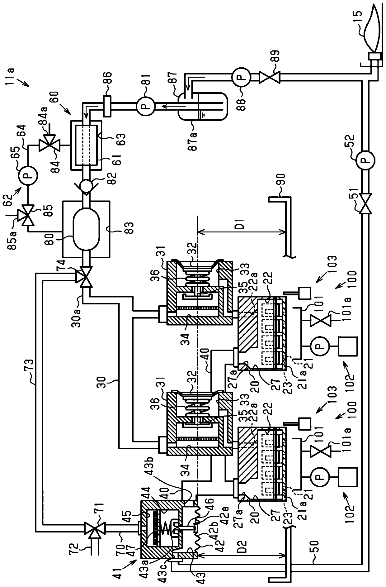
[0137] Next, a second embodiment of a liquid ejecting device and a method of controlling the liquid ejecting device will be described with reference to the drawings. In addition, this second embodiment does not include the discharge-side pressure regulating valve 41, the feedback flow channel 50, and the fluid introduction channel 70, and on the other hand, by arranging the position of the liquid tank as an example of the liquid storage part 15, the The point that the pressure applied to the nozzle 21 is adjusted is different from that of the first embodiment. In addition, since it is basically the same as the first embodiment in other points, the same reference numerals are given to the same structures to omit overlapping descriptions.
[0138] Such as Figure 8 As shown, the liquid discharge passage 40 is connected between the degassing part 60 in the liquid supply passage 30 and the supply side pressure regulating valve 31 . That is, the liquid discharge channel 40 is con...
no. 3 approach
[0163] Next, a third embodiment of the liquid ejecting device will be described with reference to the drawings. In addition, the third embodiment differs from the first embodiment in that the discharge-side pressure regulating valve 41 is not held by the head holder 90 and that the bypass passage 73 is not provided. In addition, since it is basically the same as the first embodiment in other points, the same reference numerals are given to the same structures to omit overlapping descriptions.
[0164] Such as Figure 9 as well as Figure 10 As shown, the discharge-side pressure regulating valve 41 is provided at a position where the center position of the pressure of the discharge-side liquid chamber 43 is shifted downward by a distance D5 in the vertical direction Z from the nozzle surface 21a. In addition, the discharge-side pressure regulating valve 41 is provided so that the center position of the pressure of the discharge-side liquid chamber 43 is shifted downward by a ...
PUM
 Abstract
Description
Claims
Application Information
 - R&D
- Intellectual Property
- Life Sciences
- Materials
- Tech Scout
- Unparalleled Data Quality
- Higher Quality Content
- 60% Fewer Hallucinations
Browse by: Latest US Patents, China's latest patents, Technical Efficacy Thesaurus, Application Domain, Technology Topic, Popular Technical Reports.
© 2025 PatSnap. All rights reserved.Legal|Privacy policy|Modern Slavery Act Transparency Statement|Sitemap|About US| Contact US: help@patsnap.com