Mining machine cutting arm

A technology of mining machine and cutting arm, which is applied in the field of mining machine cutting arm and ore rock working face, can solve the problems of affecting mining, insufficient undercutting and lifting amount, etc., so as to achieve flexible structure layout and improve charging effect. Effect

Pending Publication Date: 2020-08-21
SHANGHAI BRANCH TIANDI SCI&TECH CO LTD +2
View PDF0 Cites 0 Cited by
  • Summary
  • Abstract
  • Description
  • Claims
  • Application Information

AI Technical Summary

Problems solved by technology

According to conventional design rules, usually a larger cutting force means that it needs to be equipped with a larger power cutting motor, a thicker upper and lower arm cutting arm and a larger diameter drum, and the miniaturization of the mining machine requires The arm has sufficient undercut relative to the conveying device, and sufficient overhang relative to the support top beam. However, thicker cutting arms often lead to insufficient undercut and overhang, which seriously affects mining. Therefore, it is necessary to solve heavy, wide and Problems in the above-mentioned structural arrangement of thin seam mining machines with a mining height range

Method used


Image

  • Mining machine cutting arm
  • Mining machine cutting arm
  • Mining machine cutting arm

Examples


Embodiment Construction

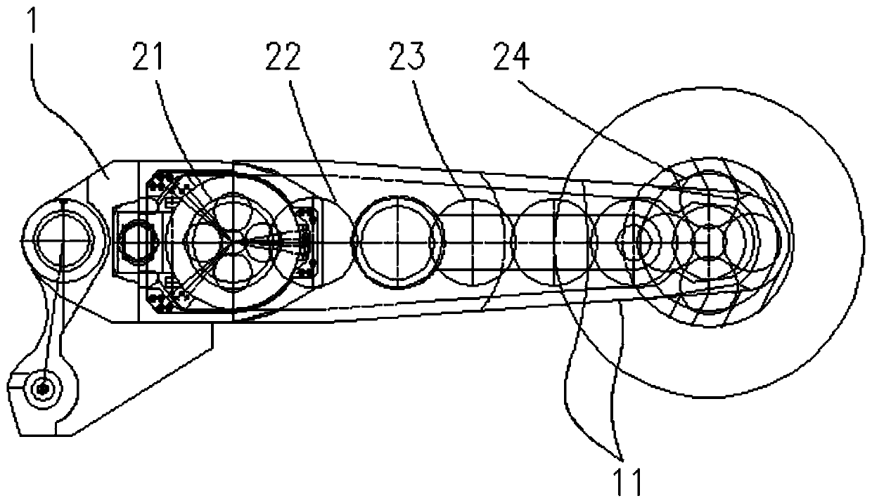
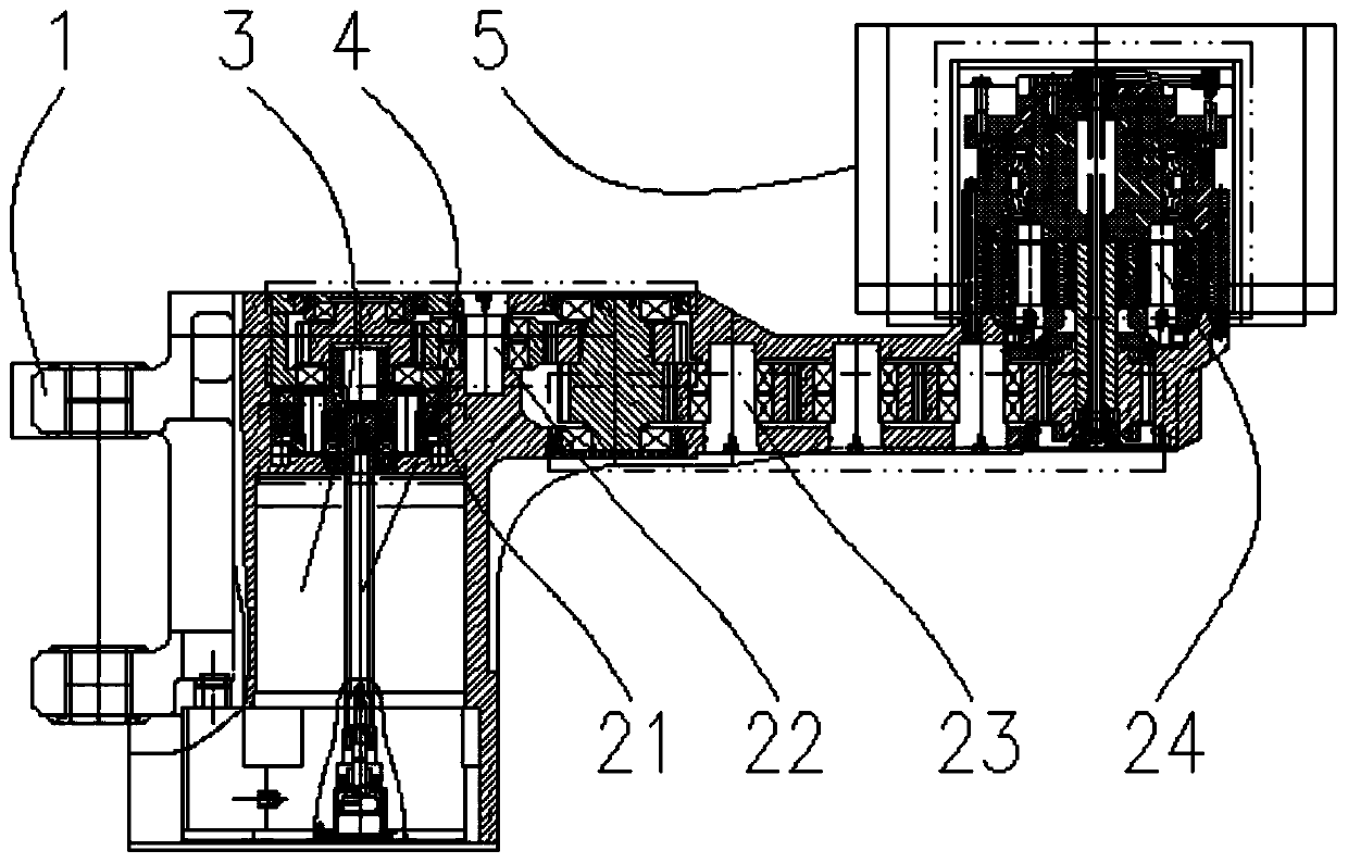
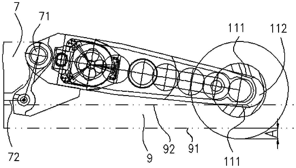
[0041] The invention discloses a mining machine cutting arm, such as Figure 1-12As shown, it includes a boom 1, a cutting motor 3, a transmission system, a clutch mechanism 4 and a small-diameter drum 5. The boom 1 is connected to the mining machine body 7 through a cutting arm connector 71 and a cutting arm cylinder 72 . In this paper, each part of the boom is named according to the distance from the fuselage when the boom is installed on the mining machine body 7 . The proximal end of the boom is provided with an installation interface structure for connecting with the mining machine body, such as connecting ear sockets. The distal end of the boom extends away from the fuselage. The arm frame includes a straight arm part, a motor mounting part protruding rearward from the proximal end of the straight arm part, and a roller mounting part protruding forward from the far end of the straight arm part. The cutting motor, transmission system and clutch mechanism are all arrang...


PUM


Abstract

The invention relates to a mining machine cutting arm. An arm rest of the mining machine cutting arm comprises a straight arm part, a motor installing part protruding backwards from the near end of the straight arm part, and a roller installing part protruding forwards from the far end of the straight arm part. A cutting motor, a transmission system and a clutch mechanism are arranged in an innercavity of the arm rest. The cutting motor is located on the motor installing part. The transmission system is arranged on the straight arm part and the roller installing part in the transmission direction from near to far. The tail level of the transmission system is located on the roller installing part, and the output end which is in transmission with the tail level coaxially fixes a small-diameter roller. The top face and the bottom face of the middle far end of the straight arm part are provided with an upper inclined plane and a lower inclined plane correspondingly, the inclination direction is the direction where the upper-lower thickness of the straight arm part is smaller when the straight arm part gets closer to the far end, and a thin-strip-shaped structure with the small upper-lower thickness is formed in the middle-far section of the straight arm part. By means of the mining machine cutting arm, a mining machine can be kept with enough downward cutting amount and roof brushing amount, and the mining machine cutting arm is suitable for exploitation of ore rock work faces large in mining range and complex in geological condition.

Description

technical field [0001] The invention relates to a cutting arm of a mining machine, which is especially suitable for a mine rock working face with a large mining range and complex geological conditions for thin ore seam mining and above, and belongs to the technical field of underground mining machinery. Background technique [0002] For the mining of thin bauxite deposits, the geological conditions are often complicated. Not only the soil-like deposits and rock-like wastes coexist, but also the thickness of the deposits varies greatly. Mining of ore deposits. According to conventional design rules, usually a larger cutting force means that it needs to be equipped with a larger power cutting motor, a thicker upper and lower arm cutting arm and a larger diameter drum, and the miniaturization of the mining machine requires The arm has sufficient undercut relative to the conveying device, and sufficient overhang relative to the support top beam. However, thicker cutting arms of...

Claims


Application Information

Patent Timeline
Patent Type & Authority Applications(China)
IPC IPC(8): E21C25/06E21C31/02E21C25/08F16H1/28E21C35/20
CPCE21C25/06E21C25/08E21C31/02E21C35/20F16H1/28
Inventor 章立强宋兆贵董超王振乾胡滔胡璟宋振何利宁顾恩洋丁海春郭岱陈阳周为伟李璐刘子亮
Owner SHANGHAI BRANCH TIANDI SCI&TECH CO LTD
Why Eureka
Try Eureka