
Continuous desilting equipment for water supply and drainage system

A technology for water supply and drainage equipment, which is applied in the field of continuous dredging equipment for water supply and drainage systems, and can solve problems such as poor stability, high water content, and difficult handling

Active Publication Date: 2020-09-29
南京迈科拓信息科技有限公司
View PDF13 Cites 0 Cited by
  • Summary
  • Abstract
  • Description
  • Claims
  • Application Information

AI Technical Summary

Problems solved by technology

However, when the above-mentioned equipment is in use, dredging is required in the process of water supply and drainage, and when the dredging equipment is dredging, there is too much water in the sludge, and at the same time, the water and the sludge cannot be separated, and it is not easy to handle in the later stage. At the same time, the stability is poor when using

Method used


Image

  • Continuous desilting equipment for water supply and drainage system
  • Continuous desilting equipment for water supply and drainage system
  • Continuous desilting equipment for water supply and drainage system

Examples


Embodiment 1

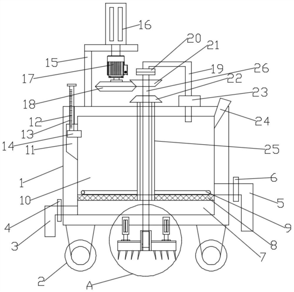
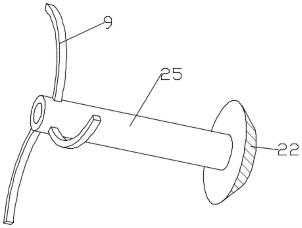
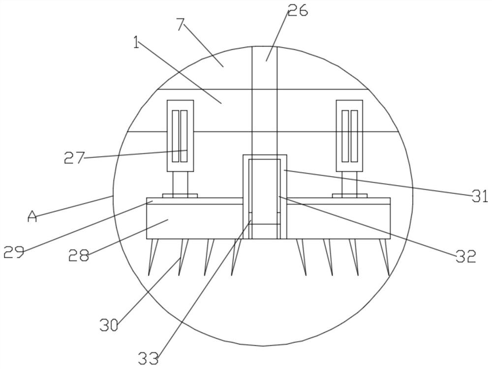
[0026] Such as Figure 1-3 As shown, in the embodiment provided by the present invention, a continuous dredging equipment for water supply and drainage system includes a box body 1, and the four corners of the lower surface of the box body 1 are provided with supporting casters 2 to facilitate the dredging equipment. the movement of the box body 1; the inner cavity of the box body 1 is divided into two chambers of the sludge chamber 10 and the sewage chamber 7 by the support net plate 8; the bottom end side of the box body 1 is provided with a 7 connected sewage discharge pipes 3, the sewage discharge pipe 3 is equipped with a sewage control valve 4; the lower side of the box 1 is also provided with a sludge discharge pipe connected to the bottom of the sludge chamber 10 5. The sludge discharge pipe 5 is provided with a sludge control valve 6; a rotating dredging pipe 26 is arranged coaxially rotating inside the box body 1, and the rotating dredging pipe 26 extending to the bo...

Embodiment 2

[0031] Such as Figure 1-3As shown, in the embodiment provided by the present invention, a continuous dredging equipment for water supply and drainage system includes a box body 1, and the four corners of the lower surface of the box body 1 are provided with supporting casters 2 to facilitate the dredging equipment. the movement of the box body 1; the inner cavity of the box body 1 is divided into two chambers of the sludge chamber 10 and the sewage chamber 7 by the support net plate 8; the bottom end side of the box body 1 is provided with a 7 connected sewage discharge pipes 3, the sewage discharge pipe 3 is equipped with a sewage control valve 4; the lower side of the box 1 is also provided with a sludge discharge pipe connected to the bottom of the sludge chamber 10 5. The sludge discharge pipe 5 is provided with a sludge control valve 6; a rotating dredging pipe 26 is arranged coaxially rotating inside the box body 1, and the rotating dredging pipe 26 extending to the bot...


PUM


Abstract

The invention relates to the technical field of water supply and drainage equipment, and particularly discloses a continuous desilting equipment for a water supply and drainage system. The continuousdesilting equipment comprises a box body. An inner chamber of the box body is divided into two chambers including a sludge chamber and a sewage chamber by a supporting screen plate. A rotary desiltingpipe is rotationally arranged in the box body coaxially. The bottom end, which extends to the position below a base plate of the box body, of the rotary desilting pipe is connected with a desilting part. The top end, which extends to the position above a top plate of the box body, of the rotary desilting pipe is connected with a fixed desilting pipe through a rotary joint. The other end of the fixed desilting pipe extends into the upper part of the sludge chamber. A desilting pump is further installed on the fixed desilting pipe. A driving motor used to drive the rotary desilting pipe to rotate is further installed on the top plate of the box body. The rotating rotary desilting pipe drives a desilting part to rotate. The continuous desilting equipment for the water supply and drainage system not only can implement continuous desilting operation, but also can separate the sludge from the sewage, and the desilting effect and the desilting efficiency of the water supply and drainage system are guaranteed.

Description

technical field [0001] The invention relates to the technical field of dredging equipment for water supply and drainage, in particular to continuous dredging equipment for water supply and drainage systems. Background technique [0002] The water supply and drainage system is a general term for providing water and waste water removal facilities for people's life, production, municipal administration and fire protection. Sometimes the water supply and drainage system will be blocked by sludge and impurities, causing some sections of the system to fail to operate normally. Therefore, relevant The device is used to dredge and remove internal impurities. [0003] In the patent document whose authorized announcement number is CN 210032072 U, a kind of pipeline dredging equipment is disclosed, wherein, the pipeline dredging equipment includes a frame; The top wall of the box is provided with an avoidance hole connected to the containing chamber; the dredging assembly includes a d...

Claims


Application Information

Patent Timeline
Patent Type & Authority Applications(China)
IPC IPC(8): E03B7/00E03C1/308E03F7/10
CPCE03B7/006E03C1/308E03F7/10
Inventor 张凯
Owner 南京迈科拓信息科技有限公司
Features
  • Generate Ideas
  • Intellectual Property
  • Life Sciences
  • Materials
  • Tech Scout
  • Unparalleled Data Quality
  • Higher Quality Content
  • 60% Fewer Hallucinations
Learn More