
High-temperature total stress-strain curve testing method and device based on optical fiber

A technology of strain curve and optical fiber, which is applied in the field of high temperature full stress-strain curve test, and can solve problems such as measurement error

Active Publication Date: 2020-10-02
NORTHWESTERN POLYTECHNICAL UNIV
View PDF13 Cites 3 Cited by
  • Summary
  • Abstract
  • Description
  • Claims
  • Application Information

AI Technical Summary

Problems solved by technology

[0006] The purpose of the present disclosure is to provide an optical fiber-based high-temperature full stress-strain curve testing method and device, a computer-readable storage medium, and electronic equipment, so as to overcome the lack of accurate stress measurement data in related technologies at least to a certain extent as a support, This will create a large measurement error problem

Method used


Image

  • High-temperature total stress-strain curve testing method and device based on optical fiber
  • High-temperature total stress-strain curve testing method and device based on optical fiber
  • High-temperature total stress-strain curve testing method and device based on optical fiber

Examples


Embodiment Construction

[0058] Example embodiments will now be described more fully with reference to the accompanying drawings. Example embodiments may, however, be embodied in many forms and should not be construed as limited to the examples set forth herein; rather, these embodiments are provided so that this disclosure will be thorough and complete and will fully convey the concept of example embodiments to those skilled in the art. The described features, structures, or characteristics may be combined in any suitable manner in one or more embodiments.

[0059]Furthermore, the drawings are merely schematic illustrations of the present disclosure and are not necessarily drawn to scale. The same reference numerals in the drawings denote the same or similar parts, and thus repeated descriptions thereof will be omitted. Some of the block diagrams shown in the drawings are functional entities and do not necessarily correspond to physically or logically separate entities. These functional entities m...


PUM


Abstract

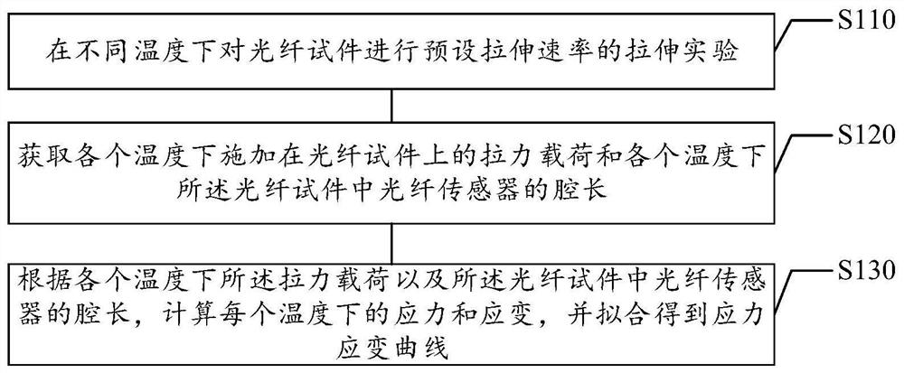
The invention relates to the technical field of optical fiber detection, in particular to a high-temperature total stress-strain curve testing method and device based on an optical fiber, and the method comprises the steps: carrying out a tensile experiment of a preset tensile rate on an optical fiber test part at different temperatures; obtaining a tension load applied to the optical fiber test part at each temperature and the cavity length of an optical fiber sensor in the optical fiber test piece at each temperature; and calculating the stress and strain at each temperature according to thetension load at each temperature and the cavity length of the optical fiber sensor in the optical fiber test part, and performing fitting to obtain a stress-strain curve. According to the technical scheme of the embodiment of the invention, the optical fiber test part is subjected to tensile experiments at different temperatures; and the stress-strain of the optical fiber sensor at each temperature is calculated according to the obtained cavity length and tension load, so accurate data can be provided for stress-strain analysis of the optical fiber sensor at different temperatures, and the actual stress-strain of the optical fiber sensor in different temperature environments can be truly measured.

Description

technical field [0001] The present disclosure relates to the technical field of optical fiber detection, in particular, to a method and device for testing a high temperature full stress-strain curve based on an optical fiber. Background technique [0002] Optical fiber sensing technology has developed rapidly and has been widely used in railways, ships, aerospace, coal mines and other projects. In the field of high-temperature materials, it is also an urgent problem to truly measure the actual stress and strain of the structure in the high-temperature environment. [0003] At present, the analysis of high temperature stress and strain is mostly based on theoretical calculations and computer simulations, lacking accurate stress measurement data as a support, which will cause large measurement errors. [0004] Therefore, it is necessary to design a new high temperature full stress-strain curve testing method and device based on optical fiber. [0005] It should be noted that...

Claims


Application Information

Patent Timeline
IPC IPC(8): G01N3/18G01N3/08G01N3/06G01L1/24G01B11/16
CPCG01N3/18G01N3/08G01N3/068G01B11/161G01L1/242G01N2203/0017G01N2203/0075G01N2203/0222G01N2203/028G01N2203/0641G01N2203/0676G01N2203/0682
Inventor 温志勋李飞刘传广吴家骥艾长胜岳珠峰
Owner NORTHWESTERN POLYTECHNICAL UNIV
Learn More