
Repairing device applied to multi-main-grid photovoltaic module

A photovoltaic module and multi-busbar technology, applied in photovoltaic power generation, electrical components, semiconductor devices, etc., can solve problems such as affecting the production capacity of components, reducing the efficiency of screw transmission, and reducing the efficiency of repairing, and achieves convenient cleaning operations and efficient lubrication. , the effect of prolonging the service life

Active Publication Date: 2020-10-09
江苏悦阳光伏科技有限公司
View PDF7 Cites 7 Cited by
  • Summary
  • Abstract
  • Description
  • Claims
  • Application Information

AI Technical Summary

Problems solved by technology

[0003] With the increase of battery busbars, the number of interconnection strips at the module end increases, which increases the difficulty of module repair and greatly reduces the repair efficiency, which affects the production capacity of modules
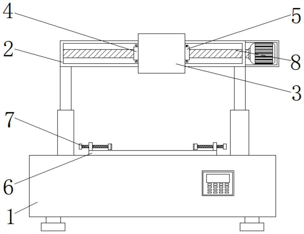
[0004] However, the existing repair devices applied to multi-busbar photovoltaic modules still have some disadvantages. After the device is used for a long time, the rotational friction of the screw in the threaded moving block becomes larger, and there is a problem of reducing the transmission efficiency of the screw; In addition, after the device has been used for a long time, too much dust has accumulated on the rotating part of the threaded moving block and the screw rod, which is inconvenient to clean up; and when the device is repairing the multi-busbar photovoltaic module, it may be affected by external factors. Affected, there is a problem of falling, so we propose a repair device applied to multi-busbar photovoltaic modules

Method used


Image

  • Repairing device applied to multi-main-grid photovoltaic module
  • Repairing device applied to multi-main-grid photovoltaic module
  • Repairing device applied to multi-main-grid photovoltaic module

Examples


Embodiment Construction

[0026] The following will clearly and completely describe the technical solutions in the embodiments of the present invention with reference to the accompanying drawings in the embodiments of the present invention. Obviously, the described embodiments are only some, not all, embodiments of the present invention. Based on the embodiments of the present invention, all other embodiments obtained by persons of ordinary skill in the art without making creative efforts belong to the protection scope of the present invention.

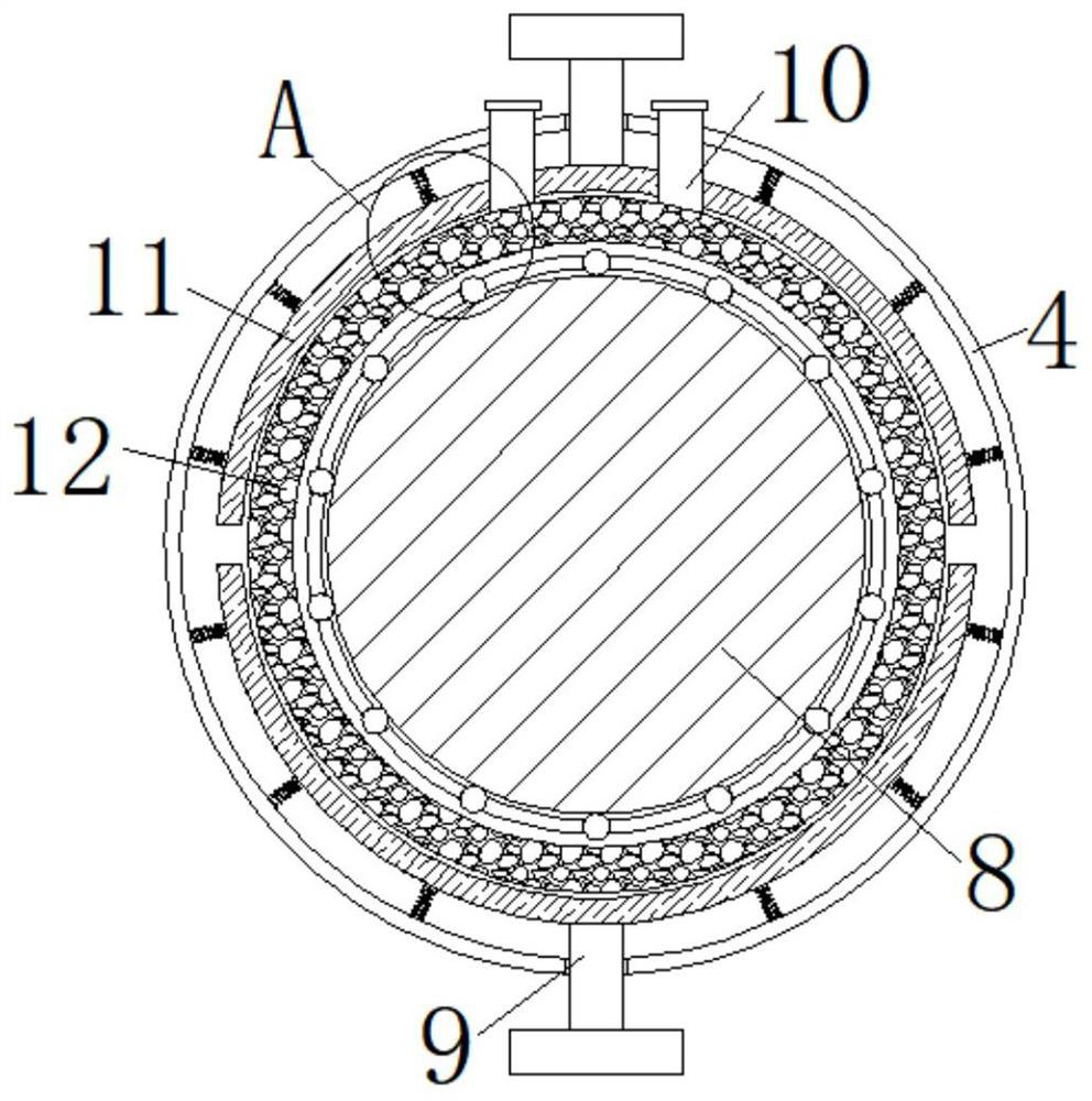
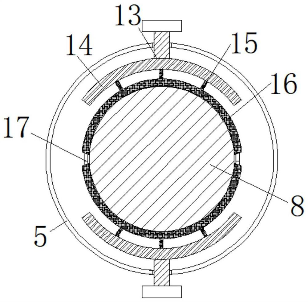
[0027] see Figure 1-5 , the present invention provides a technical solution: a repair device applied to multi-busbar photovoltaic modules, including a base 1, a beam 2 is supported and fixed on the top surface of the base 1, a motor is fixed on one side of the beam 2, and the output of the motor The shaft is rotatably connected with a screw rod 8, one end of the screw rod 8 runs through the beam 2 and extends into the inner cavity of the beam 2, the bearing o...


PUM


Abstract

The invention discloses a repairing device applied to a multi-main-grid photovoltaic module, which comprises a base, wherein a cross beam is supported and fixed on the surface of the top end of the base, a motor is fixed to the surface of one side of the cross beam, an output shaft of the motor is rotationally connected with a lead screw, one end of the lead screw penetrates through the cross beamand extends into an inner cavity of the cross beam, a threaded moving block is connected to a bearing of the lead screw in a sleeving mode, and an infrared welding lamp box is fixed to the front surface of the threaded moving block; and a lubricating sleeve and a cleaning sleeve are sequentially fixed to the surfaces of the two sides of the threaded moving block from left to right and rotationally connected to the outer wall of the lead screw in a sleeving mode. By arranging the lubricating sleeve, the surface of the lead screw can be conveniently and efficiently lubricated, and the working efficiency of the device is improved; through the arrangement of the cleaning sleeve, the surface of the lead screw can be conveniently and rapidly cleaned; and through the arrangement of the screw, the multi-main-grid photovoltaic module can be conveniently and efficiently clamped and fixed.

Description

technical field [0001] The invention belongs to the technical field of photovoltaic cells, and in particular relates to a repair device applied to multi-busbar photovoltaic components. Background technique [0002] With the development of solar photovoltaic cell and component technology, there is an increasingly urgent demand for high-efficiency components. In order to improve the efficiency of solar cells, thinner main grids and fine grids are usually used to increase the effective light-receiving area of ​​the battery. Compared with the conventional 4-5 grids, the number of battery main grid lines is increased to 6 main grids, 9 main grids, and 12 Busbar and more. [0003] With the increase of battery busbars, the number of interconnection strips at the module end increases accordingly, which makes it more difficult to repair the modules, and the repair efficiency is also greatly reduced, which affects the production capacity of the modules. [0004] However, the existin...

Claims


Application Information

Patent Timeline
Patent Type & Authority Applications(China)
IPC IPC(8): H01L31/18
CPCH01L31/18H01L31/186Y02E10/50Y02P70/50
Inventor 谭鑫张海刘波刘玉颖陈鹏苏邱
Owner 江苏悦阳光伏科技有限公司
Learn More