Supercharge Your Innovation With Domain-Expert AI Agents!

Movable mechanism for electrical cabinet door punching

A technology for moving mechanisms and electrical cabinets, applied to metal processing equipment, feeding devices, manufacturing tools, etc., can solve problems such as low efficiency and poor effect

Inactive Publication Date: 2020-10-23
胡春香
View PDF15 Cites 0 Cited by
  • Summary
  • Abstract
  • Description
  • Claims
  • Application Information

AI Technical Summary

Problems solved by technology

[0002] Existing electrical cabinets generally have hinged cabinet doors, and a small cabinet door is provided in the middle of the cabinet doors of some existing electrical cabinets to facilitate observation and maintenance without opening the entire cabinet door, which makes the cabinet When the door is being processed, it is necessary to punch holes around the small door opening of the cabinet door to facilitate the installation of the small cabinet door. The existing method is to manually punch holes during assembly. It needs to be manually fixed and then manually punched, which is inefficient. ,poor effect

Method used


Image

  • Movable mechanism for electrical cabinet door punching
  • Movable mechanism for electrical cabinet door punching
  • Movable mechanism for electrical cabinet door punching

Examples


Embodiment Construction

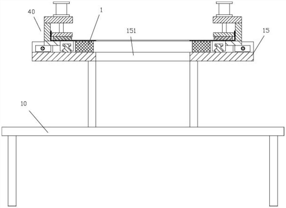
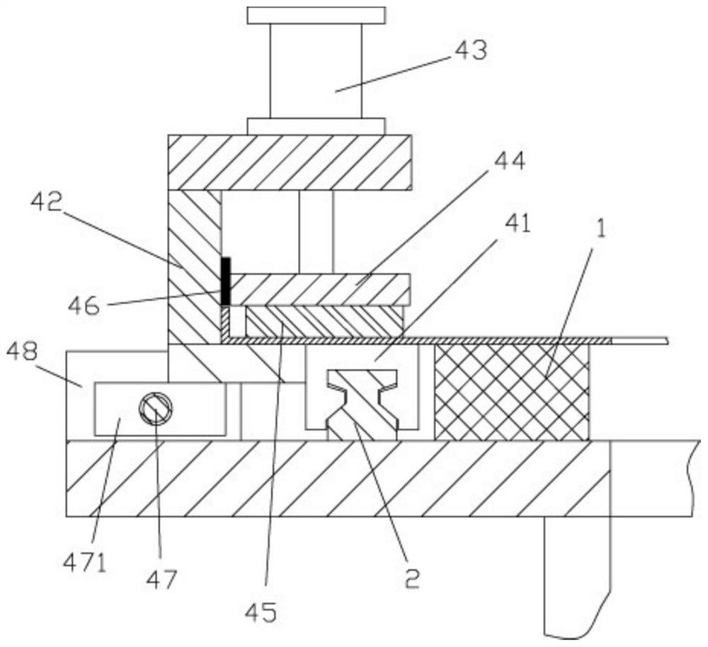
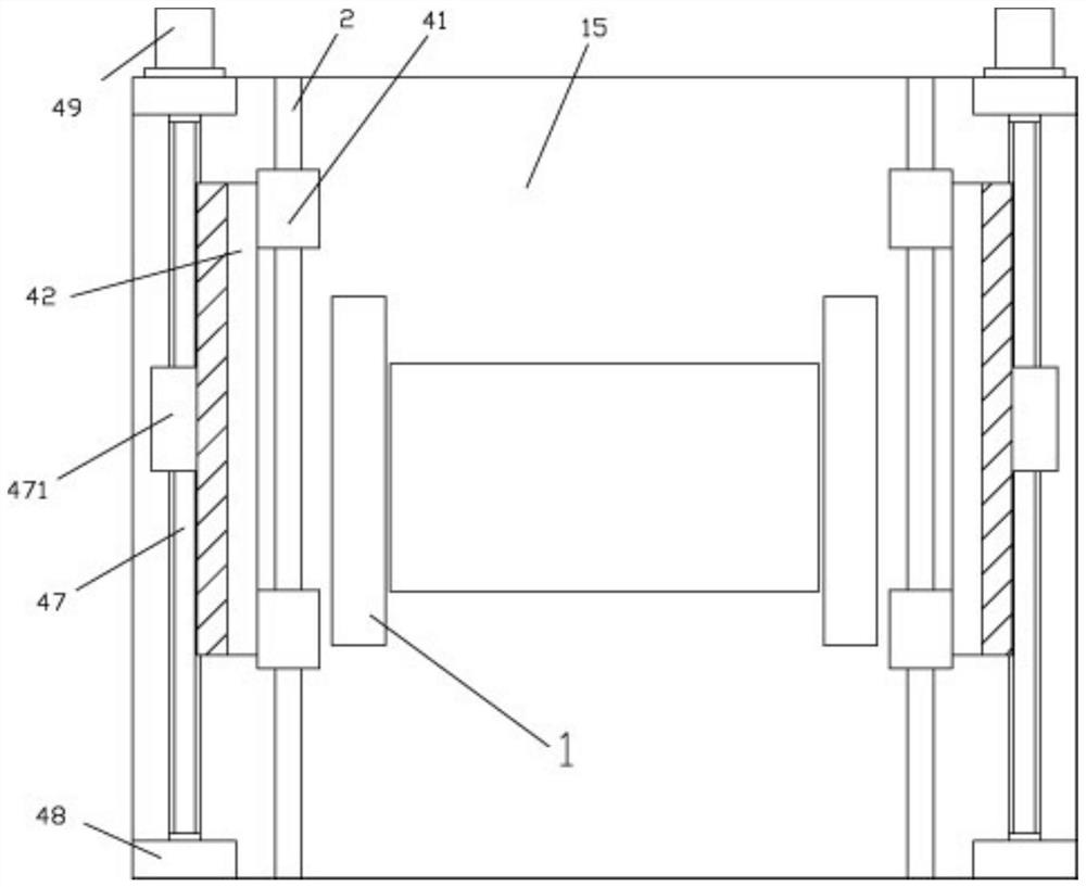
[0017] Examples, see e.g. Figure 1 to Figure 3 As shown, a moving mechanism for punching the door of an electrical cabinet includes a frame 10, the top surface of the top plate of the frame 10 is fixed with a main support frame 15, and the middle part of the top plate of the main support frame 15 has a central through groove 151 , the left and right sides of the main support frame 15 are provided with a horizontal movement mechanism 40, and the sliders 41 of the two horizontal movement mechanisms 40 are fixed with side clamping frames 42;

[0018] The top surfaces of the upper horizontal plates of the two side clamping frames 42 are fixed with a plurality of compression cylinders 43, and the push rods of all compression cylinders 43 on the same side pass through the corresponding upper horizontal plates and are fixed on the same compression cylinder extending forward and backward. On the top surface of the tight bar 44 , an electromagnet bar 45 is fixed on the bottom surface ...


PUM


Abstract

The invention discloses a movable mechanism for electrical cabinet door punching. The movable mechanism comprises a rack, a main supporting frame is fixed to the top face of a top plate of the rack, and a center through groove is formed in the middle of the top plate of the main supporting frame. Horizontal movable mechanisms are arranged on the left side and the right side of the main supportingframe, and lateral clamping frames are fixed to sliding blocks of the two horizontal movable mechanisms. Multiple compressing air cylinders are fixed to the top faces of upper horizontal plates of thetwo lateral clamping frames, and push rods of all the compressing air cylinders on the same side penetrate through the corresponding upper horizontal plates and are fixed to the top face of the samecompressing strip extending front and back. Electromagnet strips are fixed to the bottom faces of the compressing strips, and the electromagnet strips correspond to the top faces of the lower connecting parts of the lateral clamping frames. According to the movable mechanism, a cabinet door can be clamped, fixed and moved front and back, manual positioning punching is convenient, or the movable mechanism can be mounted on an automatic punching mechanical component, and automatic punching is convenient.

Description

Technical field: [0001] The invention relates to the technical field of making electric cabinets, and more specifically relates to a moving mechanism for punching holes in the doors of electric cabinets. Background technique: [0002] Existing electrical cabinets generally have hinged cabinet doors, and a small cabinet door is provided in the middle of the cabinet doors of some existing electrical cabinets to facilitate observation and maintenance without opening the entire cabinet door, which makes the cabinet When the door is being processed, it is necessary to punch holes around the small door opening of the cabinet door to facilitate the installation of the small cabinet door. The existing method is to manually punch holes during assembly. It needs to be manually fixed and then manually punched, which is inefficient. ,poor effect. Invention content: [0003] The purpose of the present invention is to overcome the deficiencies of the prior art and provide a moving mech...

Claims


Application Information

Patent Timeline
IPC IPC(8): B21D28/26B21D43/00
CPCB21D28/26B21D43/003
Inventor 胡春香
Owner 胡春香
Features
  • R&D
  • Intellectual Property
  • Life Sciences
  • Materials
  • Tech Scout
  • Unparalleled Data Quality
  • Higher Quality Content
  • 60% Fewer Hallucinations
Learn More