Supercharge Your Innovation With Domain-Expert AI Agents!

Current collecting ring rotor module and manufacturing method thereof

A manufacturing method and collector ring technology, which is applied in the manufacture of slip rings, current collectors, and rotating collectors, can solve the problems of complex manufacturing methods and the inability to organize the wires connected to the stator

Inactive Publication Date: 2020-10-27
TRICORE CORP
View PDF6 Cites 0 Cited by
  • Summary
  • Abstract
  • Description
  • Claims
  • Application Information

AI Technical Summary

Problems solved by technology

Generally speaking, the manufacturing method of the slip ring rotor is to stack the metal ring and the insulating ring axially to ensure the insulation between adjacent slip rings, or to assemble the assembled insulating metal ring components into shape, However, this production method is still complicated, and it is impossible to organize the wires connected to the stator

Method used


Image

  • Current collecting ring rotor module and manufacturing method thereof
  • Current collecting ring rotor module and manufacturing method thereof
  • Current collecting ring rotor module and manufacturing method thereof

Examples


Embodiment Construction

[0017] In order to clearly illustrate the specific implementation mode, structure and achieved effects of the present invention, the illustrations are as follows:

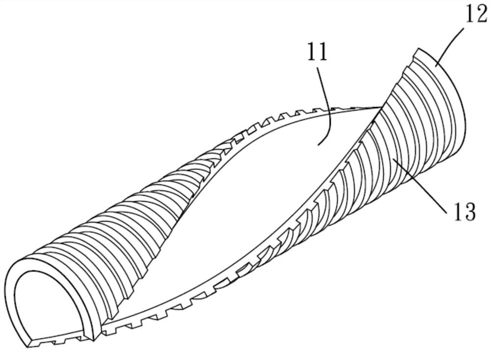
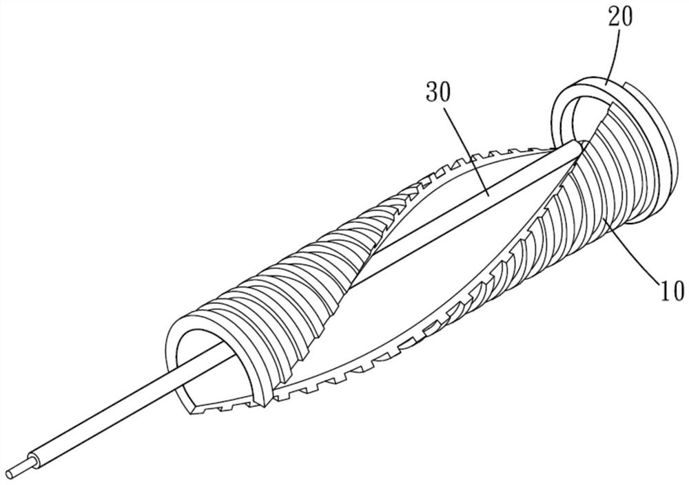
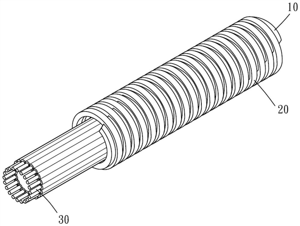
[0018] see figure 1 , shows a structure of a positioning member 10. The positioning member 10 has a side wall that spirally surrounds along the imaginary axis, and the side wall has an inner wall surface 11 facing the virtual axis and an outer wall surface 12 away from the virtual axis. The outer wall surface 12 defines a slightly cylindrical conductive ring positioning area, and is connected with the conductive ring 20 (such as figure 2 shown) in partial contact with the inner ring surface. In other words, the side wall has a spiral outer edge, so that the contact surfaces between the outer wall surface 12 and each conductive ring 20 do not form a closed contour. In addition, the material of the positioning member 10 is an insulator as a whole, and the outer wall surface 12 also has a plurality of conductive ri...


PUM


Abstract

The invention provides a current collecting ring rotor module, which comprises a positioning piece, a plurality of conducting rings stacked along the virtual axial direction of the positioning piece and a plurality of conducting wires respectively and electrically connected with the conducting rings, wherein the positioning piece is provided with a side wall which is spiral along the virtual axialdirection. According to the invention, the conducting ring is assembled on the outer side of the side wall of the positioning piece, and the conducting wire is located on the inner side of the side wall of the positioning piece, so that the positioning piece can be omitted, and the current collecting ring rotor module assembling procedure is simplified.

Description

technical field [0001] The invention relates to a slip ring rotor module, more precisely, to a slip ring rotor modular structure which can simplify the assembly process. Background technique [0002] The cooperation of the slip ring rotor and the brush can be applied in electromechanical systems that require continuous rotation and transmission of power and / or signals to avoid sprains caused by wires during rotation. Generally speaking, the manufacturing method of the slip ring rotor is to stack the metal ring and the insulating ring axially to ensure the insulation between adjacent slip rings, or to assemble the assembled insulating metal ring components into shape, However, this manufacturing method is still complicated, and it is impossible to organize the wires connected to the stator. Contents of the invention [0003] In view of this, the present invention provides a slip ring rotor module, which includes a positioning member, a plurality of conductive rings nested ...

Claims


Application Information

Patent Timeline
IPC IPC(8): H01R39/08H01R39/34H01R43/10
CPCH01R39/08H01R39/34H01R43/10
Inventor 施心智洪宗宇
Owner TRICORE CORP
Features
  • R&D
  • Intellectual Property
  • Life Sciences
  • Materials
  • Tech Scout
  • Unparalleled Data Quality
  • Higher Quality Content
  • 60% Fewer Hallucinations
Learn More